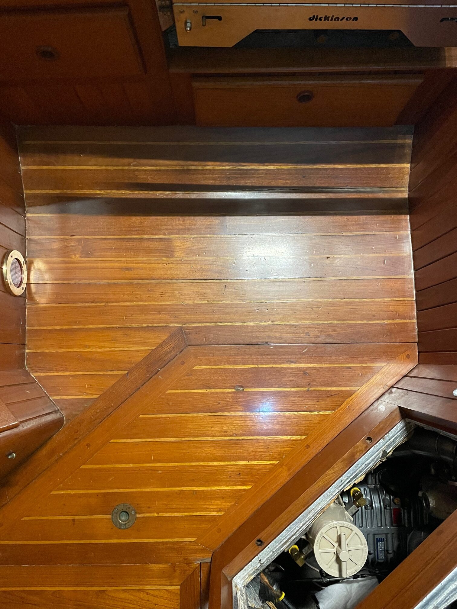
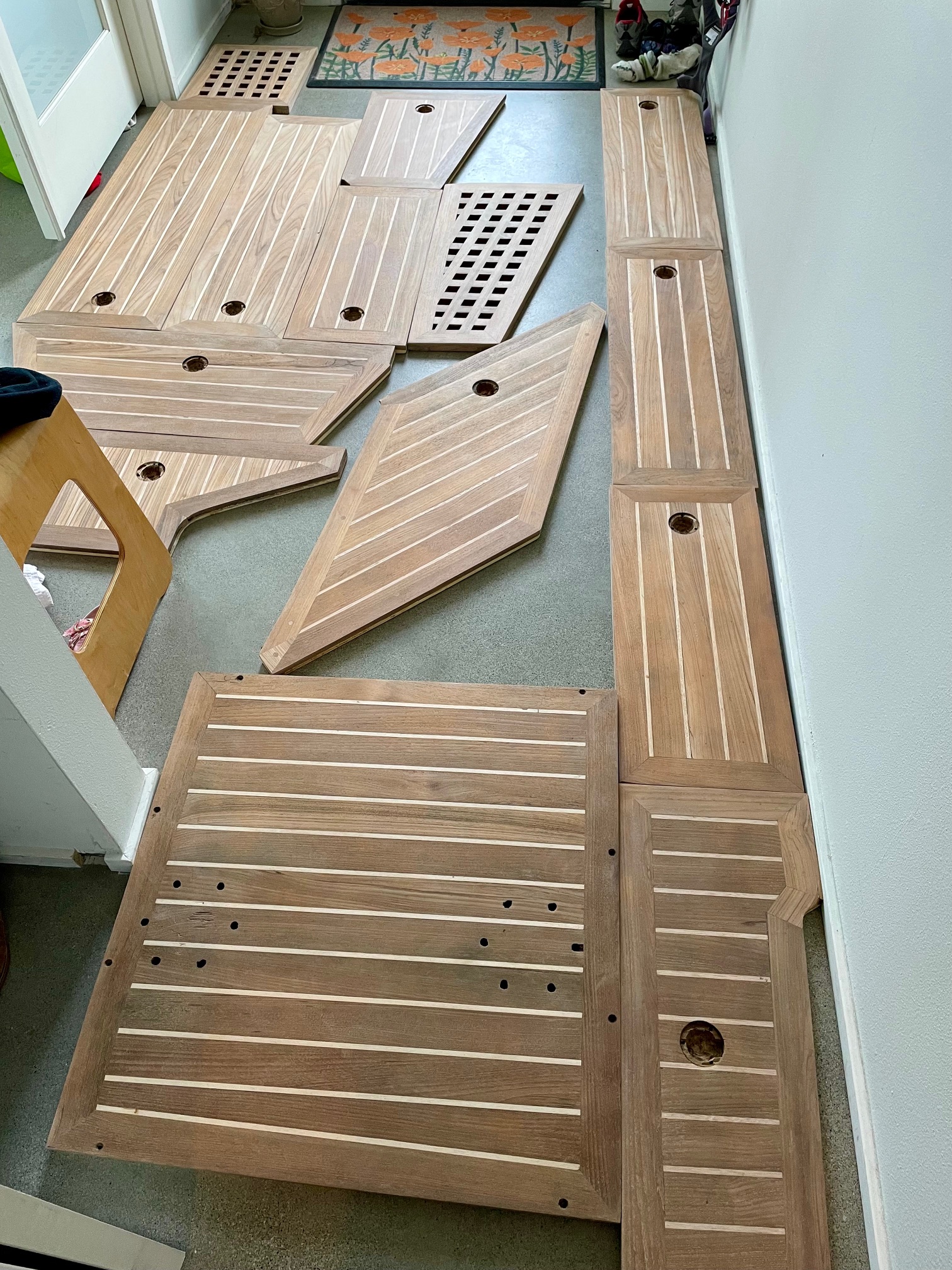
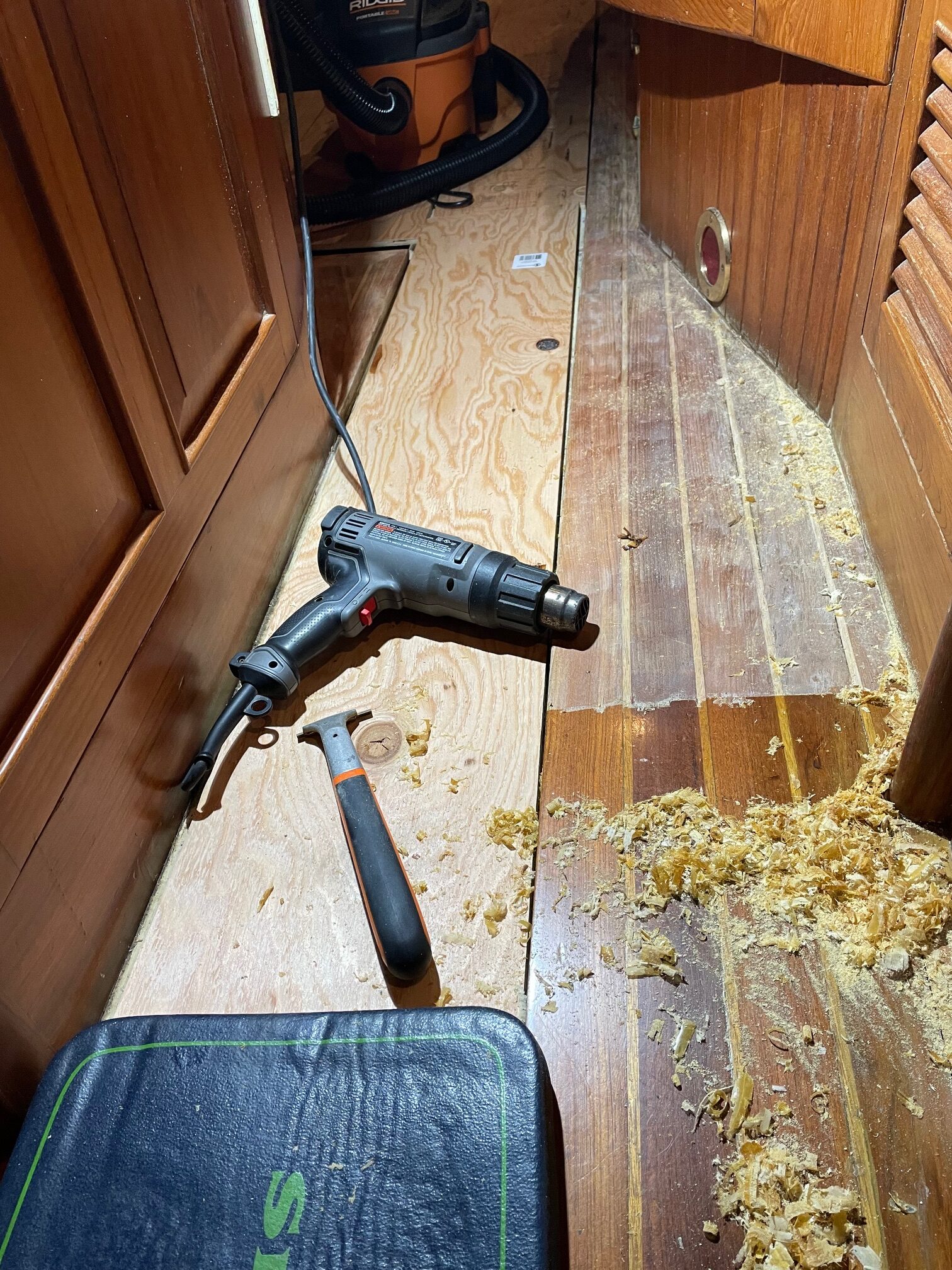
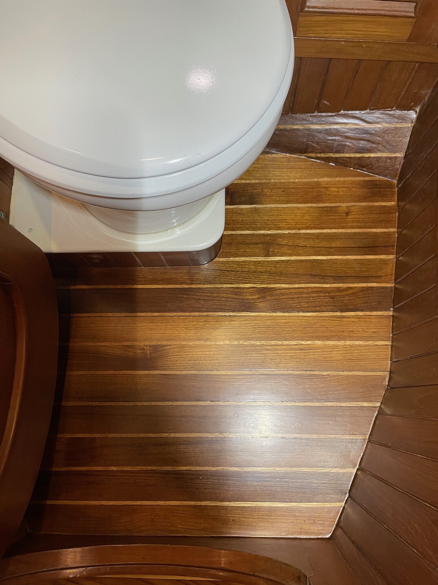
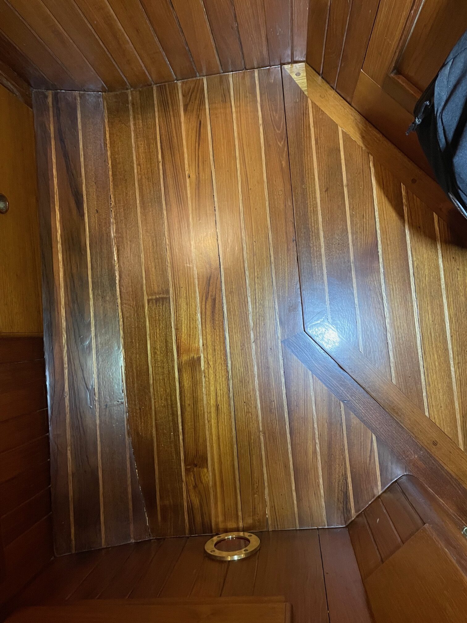
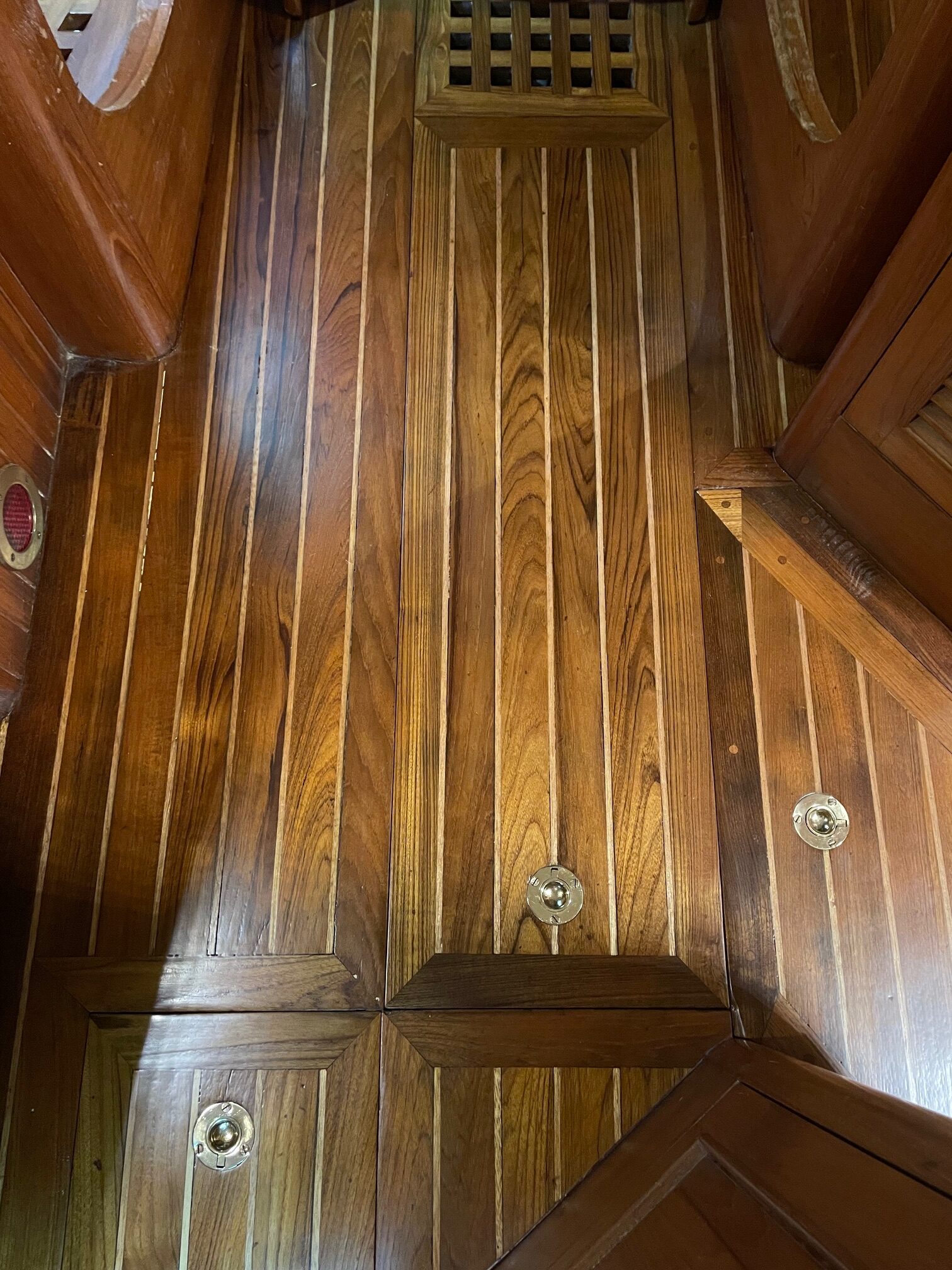
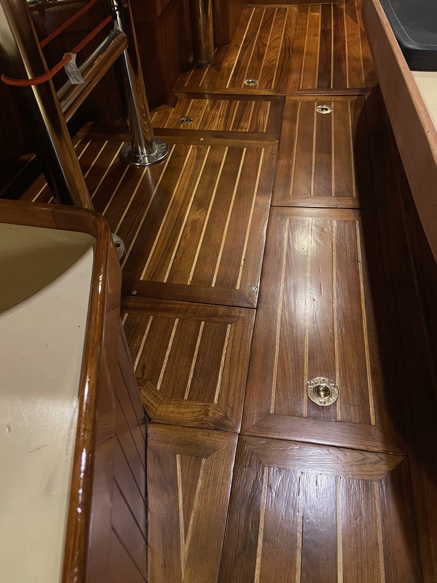
When we bought Apropos in 2005, the teak cabin sole was in good shape for a 22 year old boat. The boat was lightly used during those 22 years and actually sat unused for 10 of those years. But after owning the boat for 21 years and sailing an estimated 25,000 miles, the finishing on the cabin sole was worn, with plenty of scuffs and scratches and even some dents from things flying around the cabin. So I decided to refinish the entire cabin sole. Shown below are a few pictures taken before I began–on the left is the galley floor and on the right is a panel that lies next to the part of the setee that is movable for accessing the front side of the engine. That section slides along the top of this panel, and has damaged the finish.
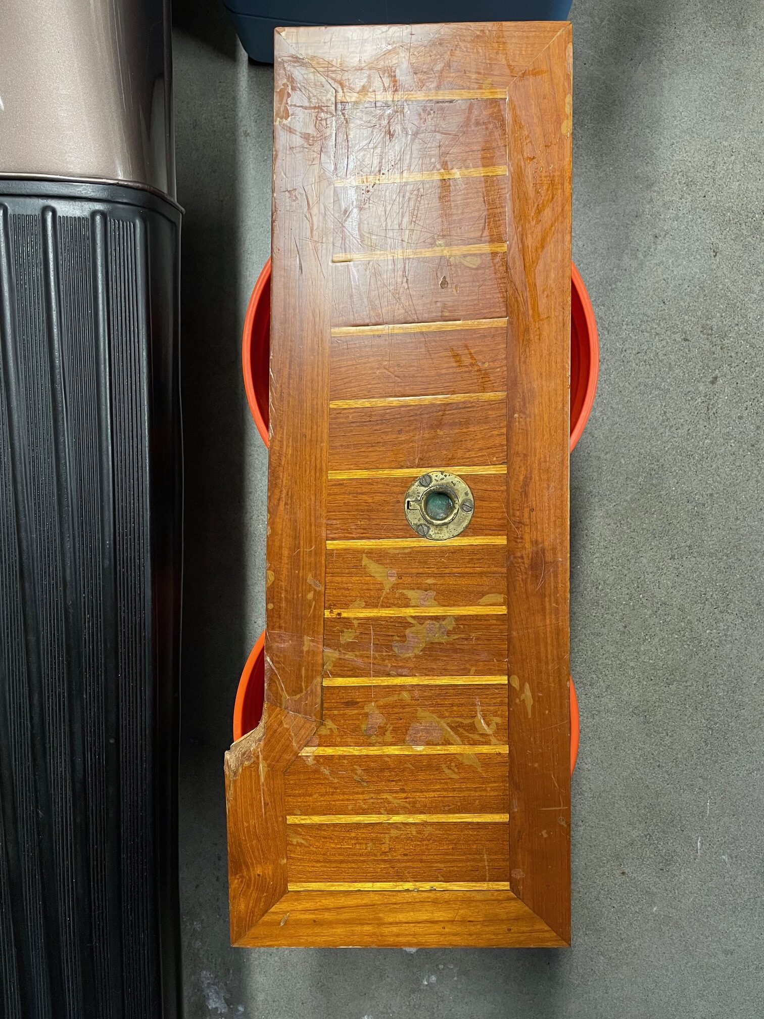
The sole is made of 2″ wide solid teak planks with 1/4″ strips of holly. Both teak and holly are rot-resistant hardwoods. The combination is a traditional look the provides a nice contrast between the dark teak and light holly. The solid teak and holly are 3/8″ thick, and glued to 9/16″ thick marine hardwood. Boats made in the 1970’s-1980’s used old growth teak which was plentiful 50 years ago. Today, most teak is plantation grown and what very few boats that use teak, use only a thin veneer over plywood.
3/8″ Teak on left, 9/16″ hardwood on right
There are 14 removable panels, equaling about 2/3rd of the entire sole. These can all be removed and taken off the boat for ease of refinishing. The remainder is non-removable and will be refinished in-place on the boat.
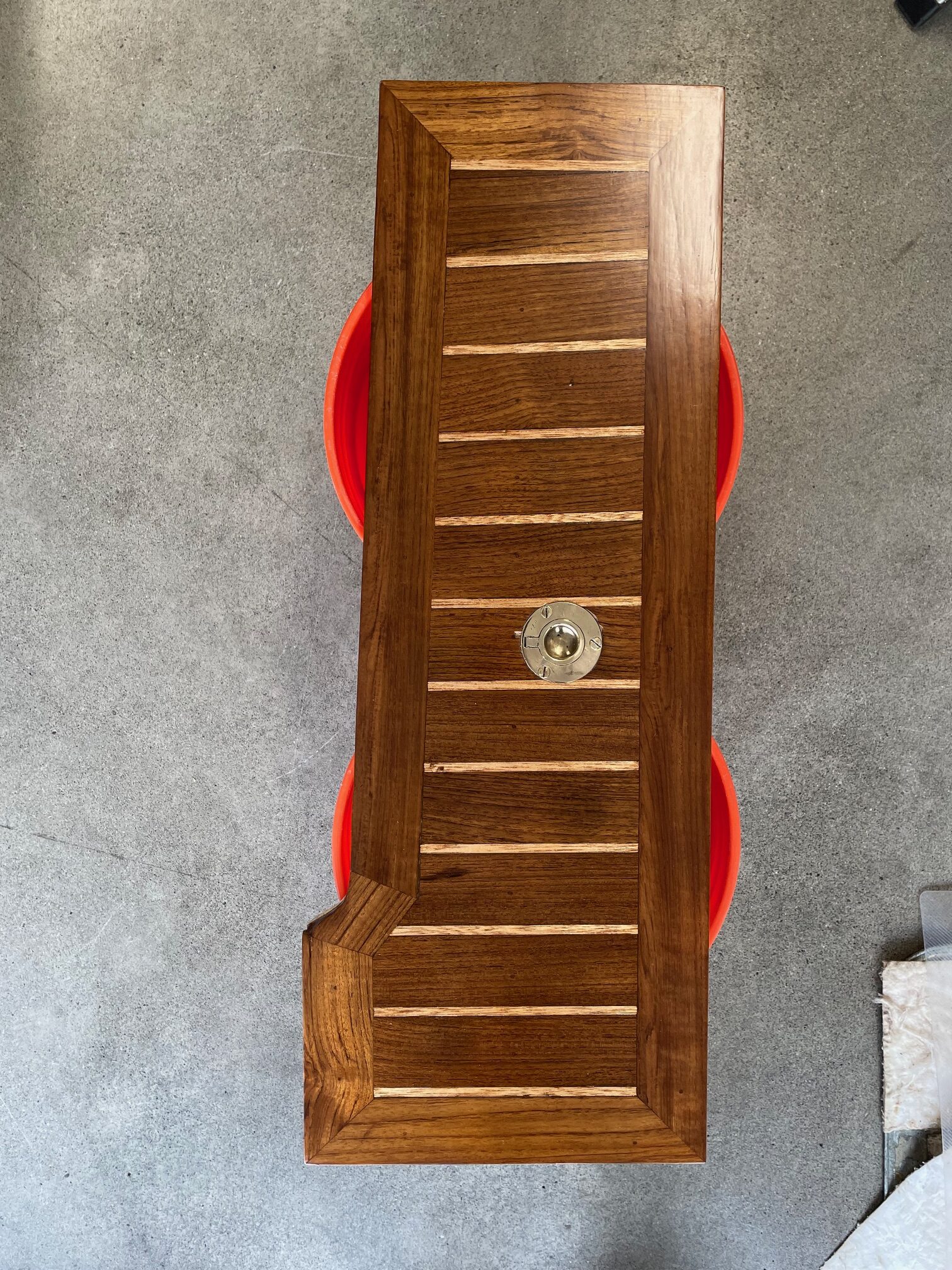
I decided to use Awlwood products to refinish the sole. I’m very familiar with them from refinishing the entire exterior brightwork on Apropos. Instead of a yellow primer that I used on the exterior teak, I used a clear primer for the interior so the holly strips remain brighter for a better contrast with the darker teak. Then I applied 6 coats of clear gloss and a final 2 coats of clear matte.
Preparation
I took the removable panels off the boat to refinish. Here are the steps I followed:
Remove brass hardware (pull rings)
Apply a chemical stripper and allow to sit overnight
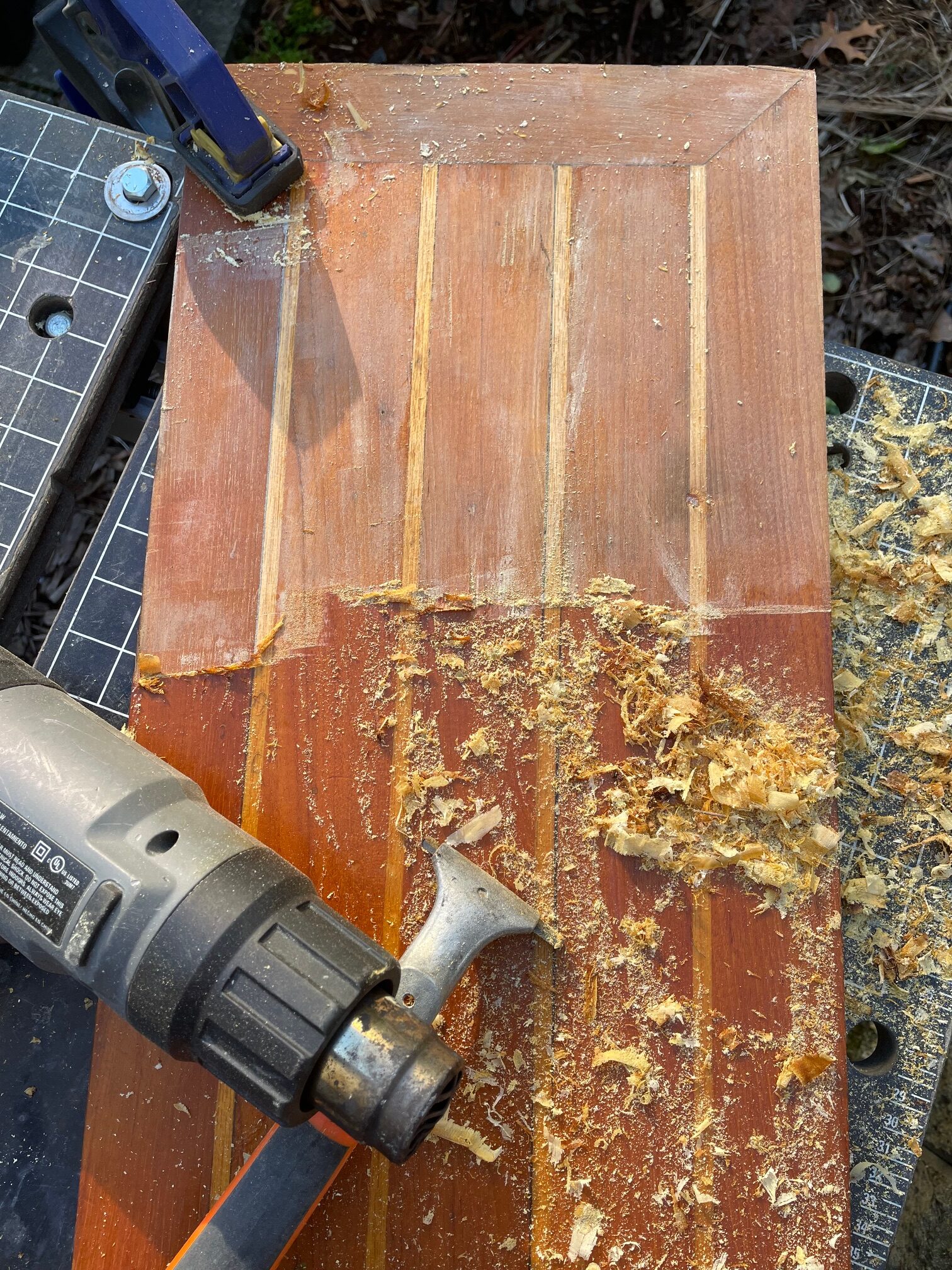
Use a heat gun and scraper to remove the old varnish
Use an orbital sander with 80 grit then 240 grit
Apply clear primer
Apply 6 coats of clear gloss
Apply 2 coats of clear matte
Polish and reinstall brass hardware
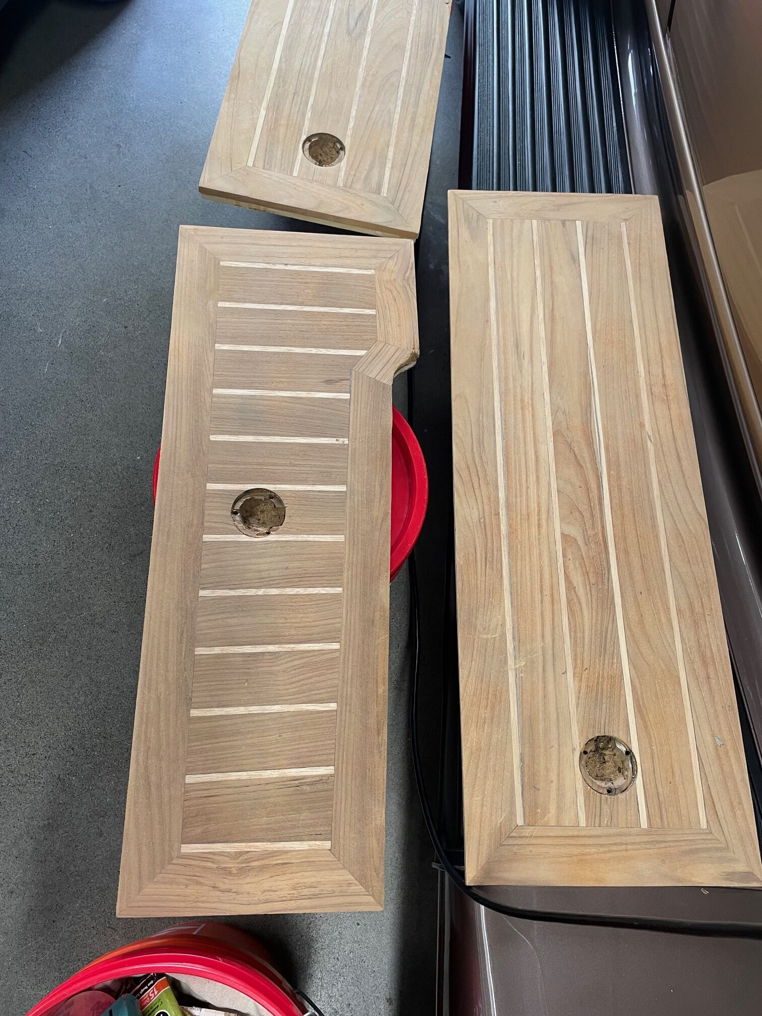
The holly on Apropos sole appeared yellow because of the tint in the varnish. After stripping off the varnish and sanding, the holly is almost white. The finishing I’m using (Awlwood primer and clear) should do a better job at keeping the holly bright.
Removing VarnishScraped & SandedReady for Primer
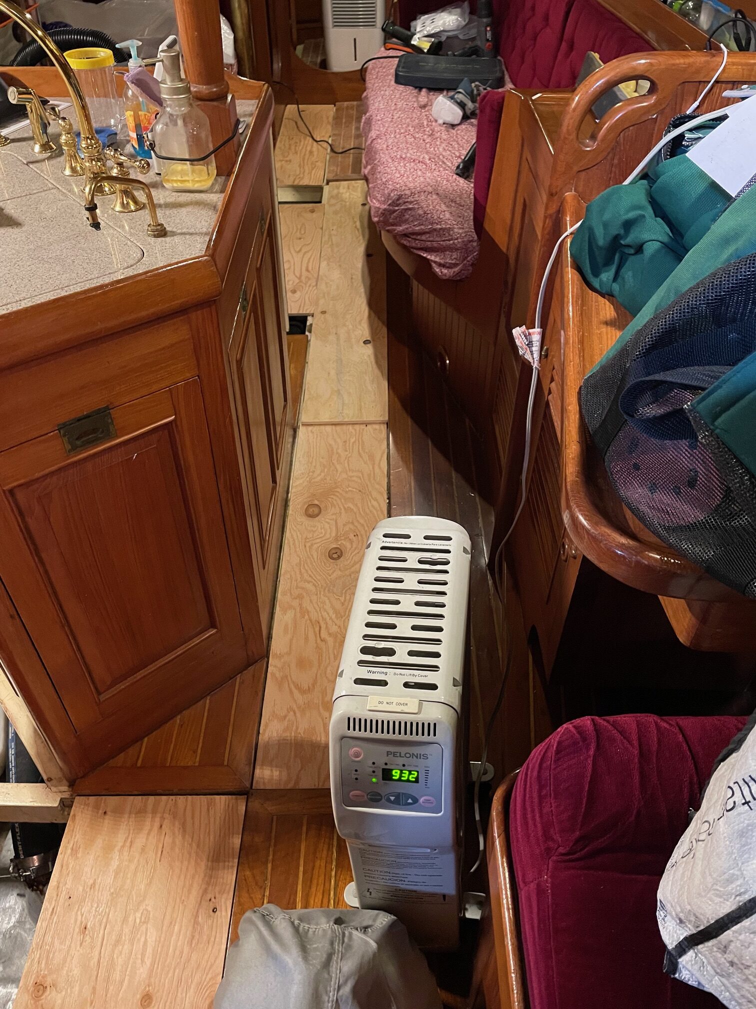
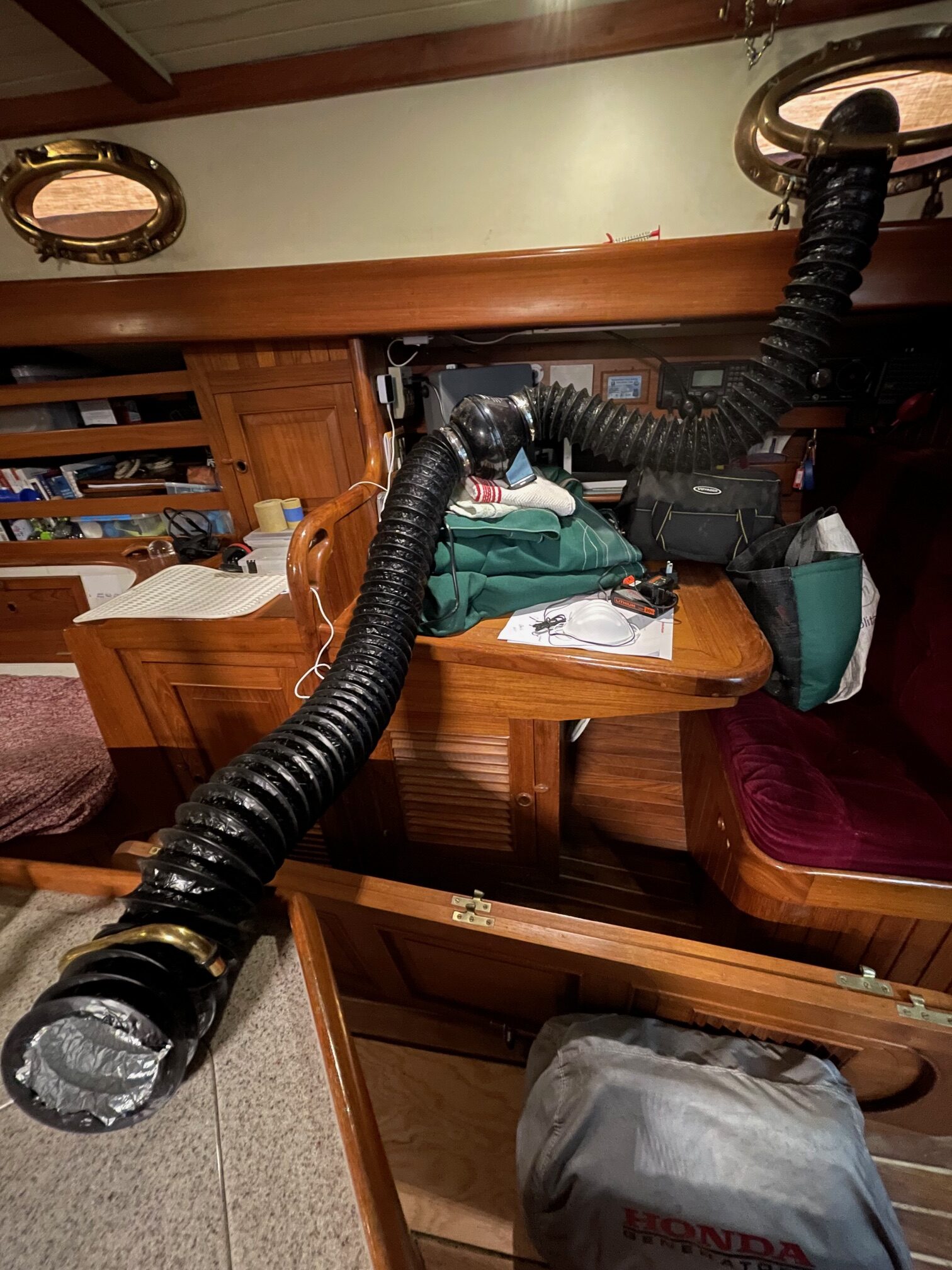
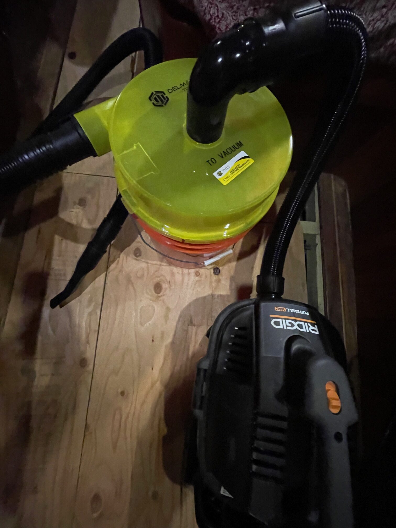
For the non-removable sections of the sole, the process was a lot more difficult. From a full sheet of plywood, I cut various shapes to take the place of the removed panels and make walking around easier. Heating, scraping, and sanding were messy. The orbital palm sander put dust everywhere. Goggles and a good respirator were important protections from dust and chemical fumes. When sanding, I ran a duct fan with 4″ hoses from the area where I was working, out through a port to the outside of the boat. At 195 cfm, this helped remove a lot of the dust in the air. I also used a good shop vacuum with a dust separator while scraping and sanding. I ran a dehumidifier and heater to get better climate control for working and applying finishes.
Primer Coat
After final sanding and using compressed air to remove the fine saw dust, I applied a coat of Awlwood Clear Primer. This helps seal the wood and prepare for building the layers of Clear Gloss. Even though there was no pigment in the primer, it gave the teak a darker tone while still keeping the holly bright.
Clear Coats
After a light sanding of the primer, I applied 6 coats of Awlwood Gloss, sanding after every 2 coats. I used Awlwood Matte for coats 7 and 8 to give it a less shiny look and make it less slippery. Here’s a before and after photo of one of the panels.
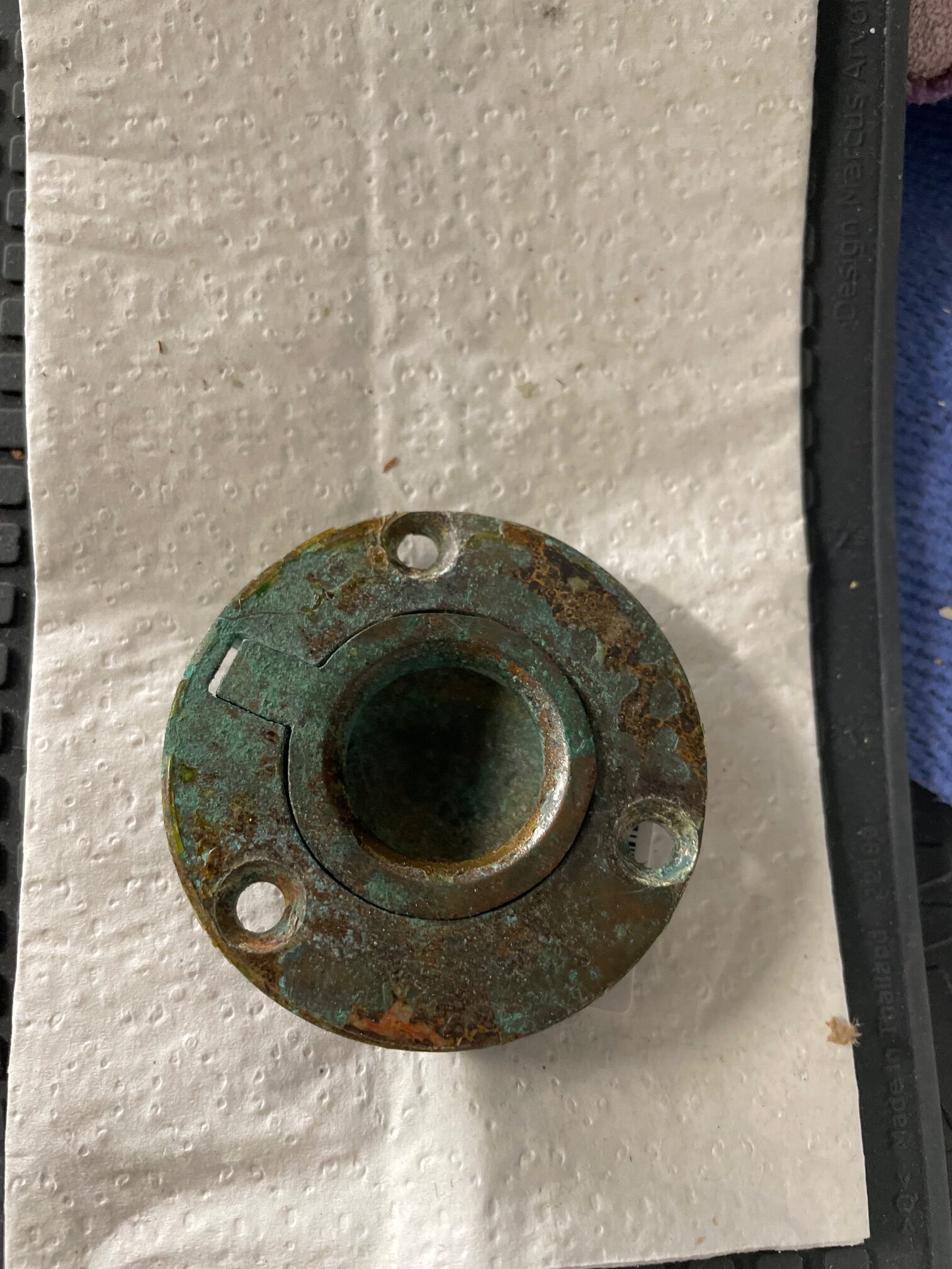
Brass Pull Rings
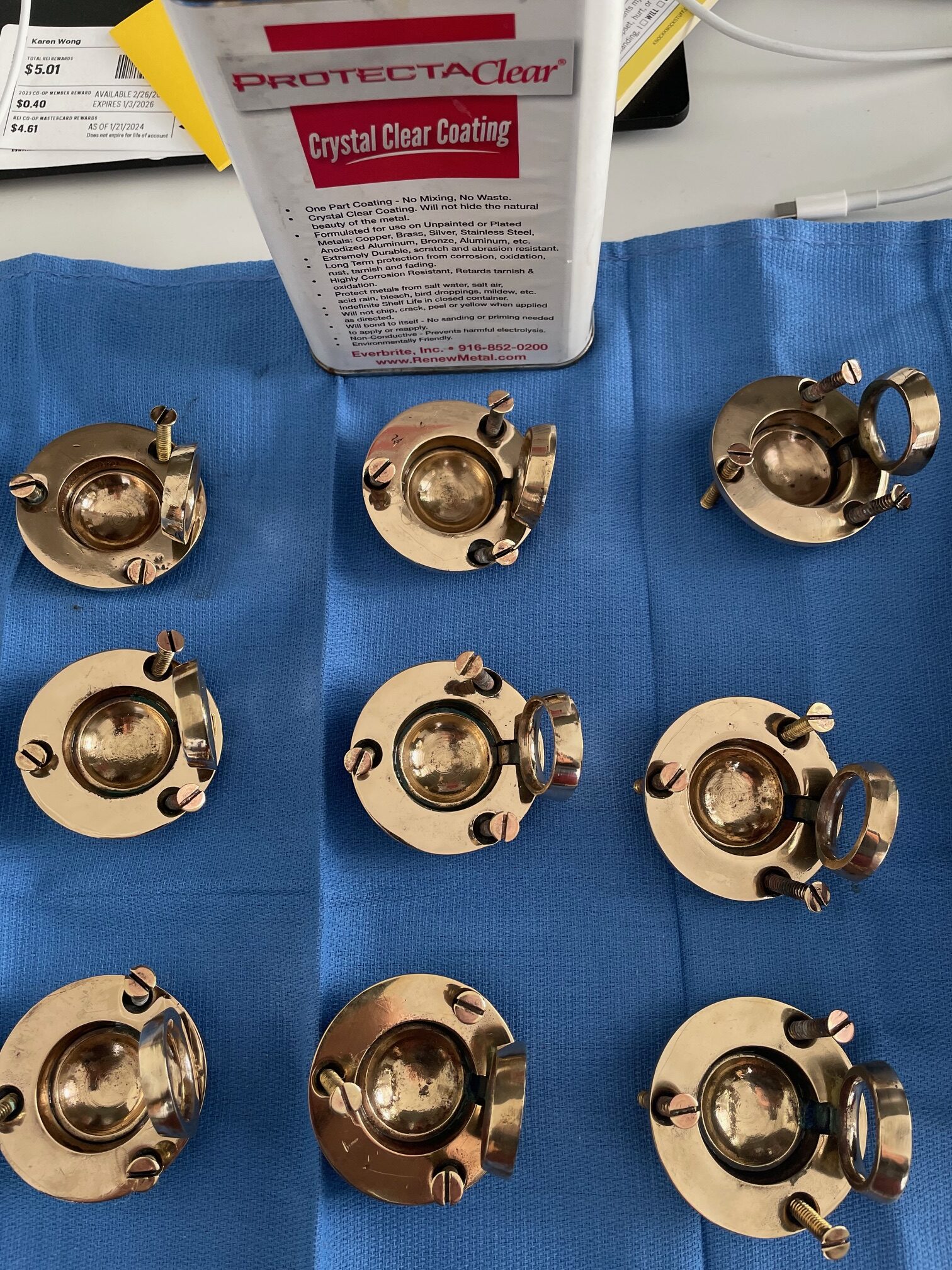
Using a wheel polisher with buffing compounds, I was able to make the brass pull rings shiny again. After polishing, I coated them with 6 layers of ProtectaClear. I’ve had good luck with using ProtectaClear on interior brass parts such as galley faucets and hatch hardware, but not sure how durable it will be on parts that will be walked on.
Conclusion
The project took about a month from start to finish. It was a lot of hard work but the results were very satisfying.
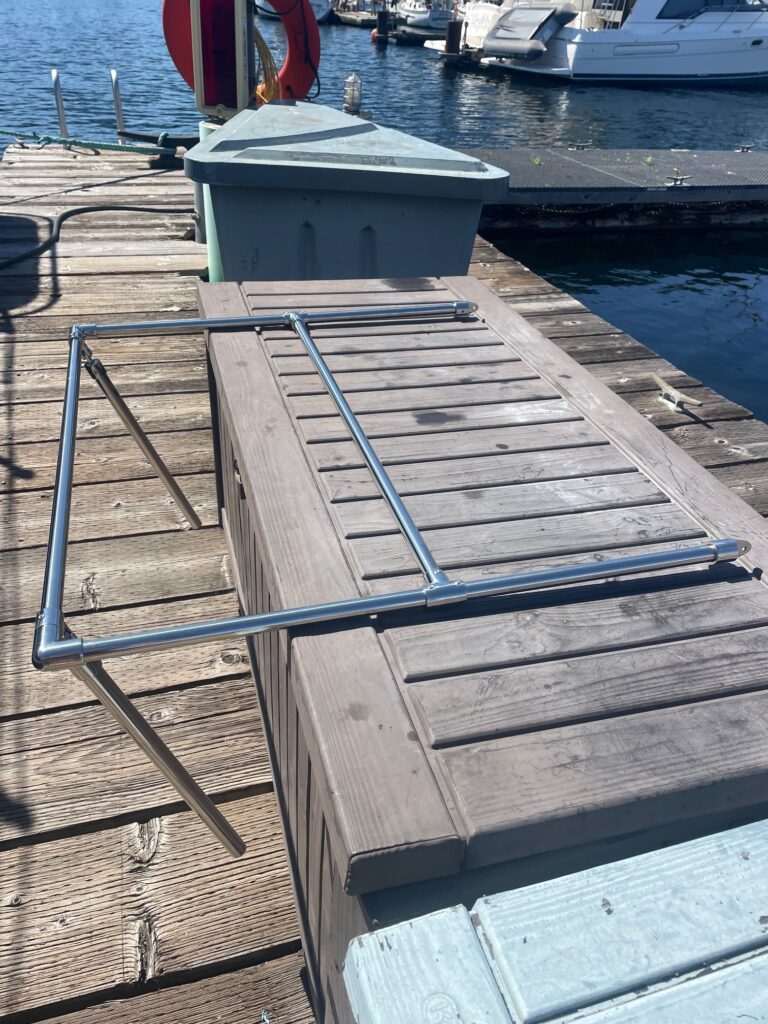
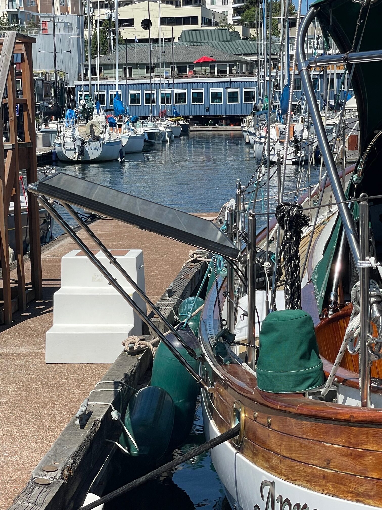
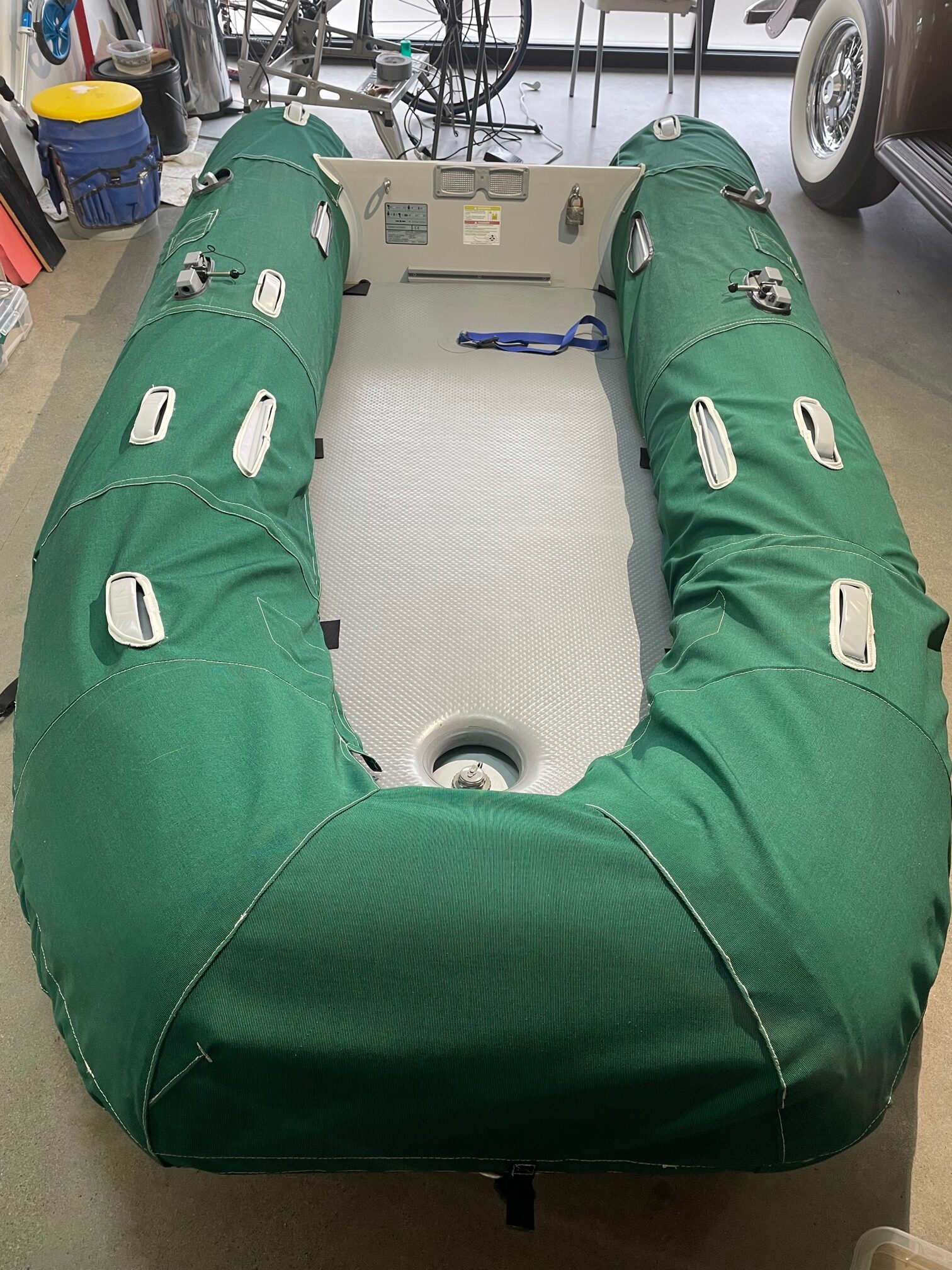
The solar panels that I had installed on Apropos were now 12 years old. They consisted of 2-85W, 2-95W, and 1-135W panels for a total of 495W. PV cells and solar panels have come a long way in 12 years. Increases in efficiency, flexible panels that can be walked on, bi-facial panels and better solar controllers are some of the changes that have occurred over the past years. Also, the price of solar cells have decreased dramatically.
The old solar panels were aboard Apropos during the 2014-15 trip to the South Pacific. The 2-85W panels sat on the deck against the butterfly hatch port and starboard, 2-95W panels were mounted outboard the lifelines port and starboard, and a 135W panel atop the dodger. The 2 on the deck were easily moved while at anchor to either side depending on the sun position. The system worked well and we were able to run all the electronics and have refrigeration and watermaker (run only with engine). We didn’t use autopilot (windvane was used instead) and had to shut down the freezer due to its frequent cycling.
There were several goals in upgrading the solar. More total PV watts, better placement of panels, better panel adjustments, and easier/quicker removal of panels from outboard mounts.
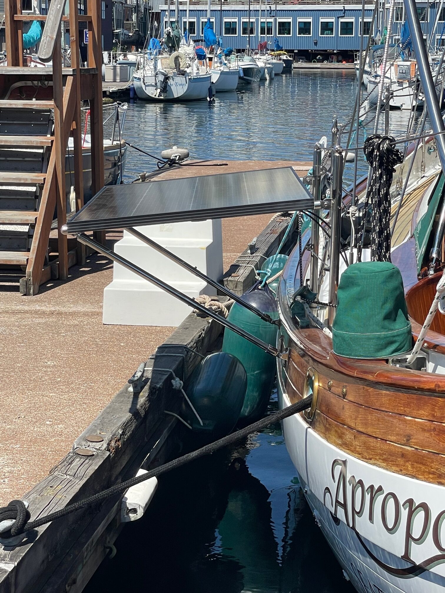
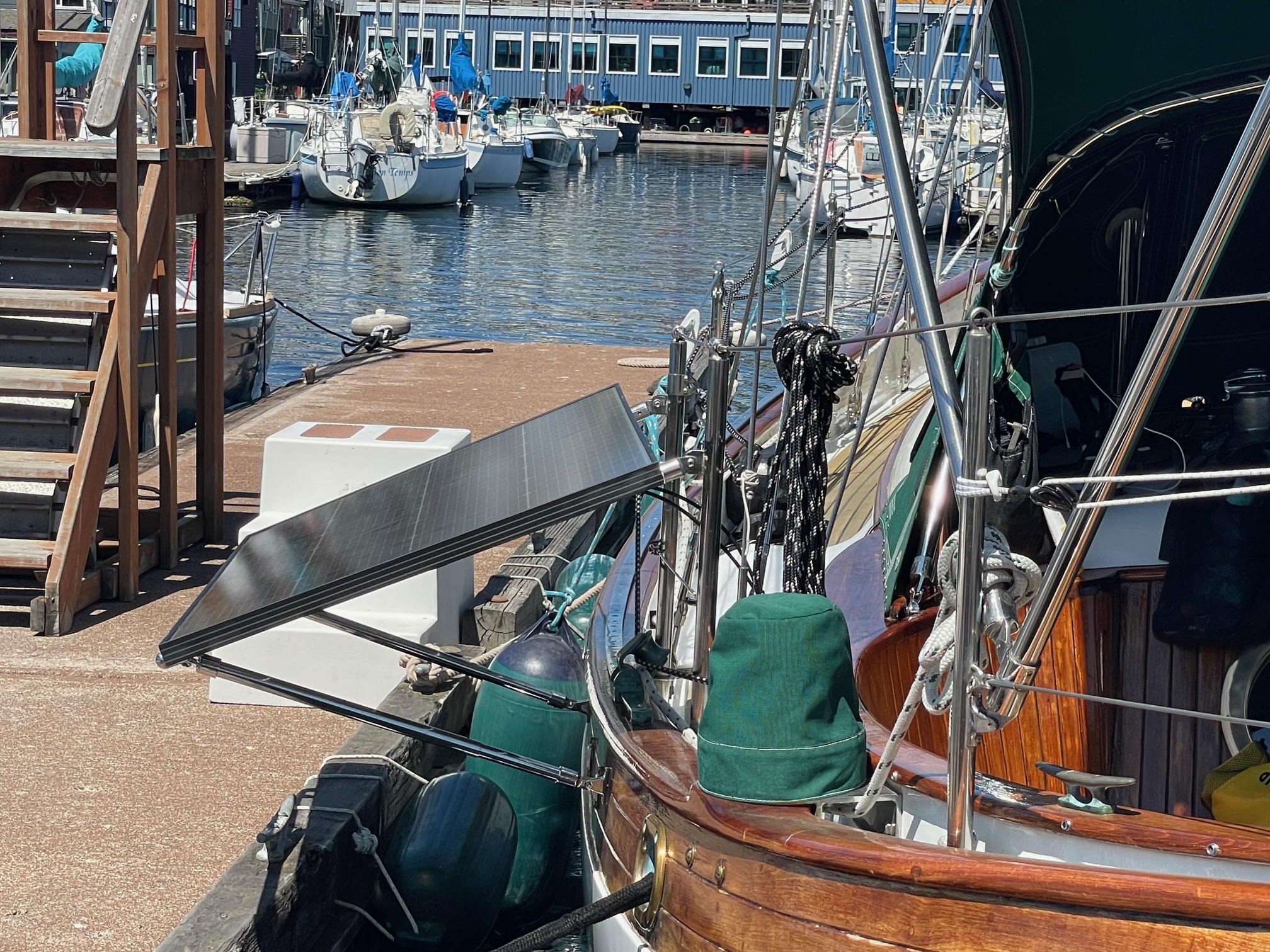
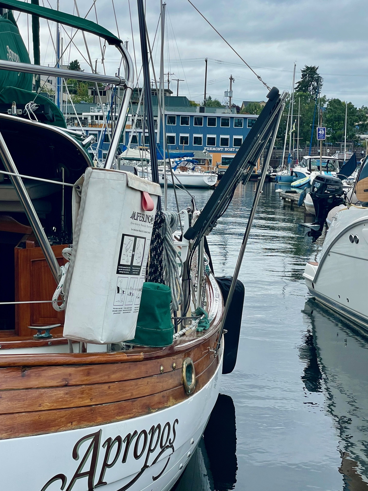
The new solar panels are 2-200W bifacial monocrystalline. Bifacial panels have additional, lower-grade solar cells on the backside of the panel to increase the efficiency/area. Most rooftop mounts can’t take advantage of bifacial panels, but the outboard mounts on a boat are ideal for bifacial panels where UV rays reflect off the water and hit the backside. The new 200W panels are approximately 30″ x 54″, 50% bigger than the 95W panels and 100% more wattage.
Mounting
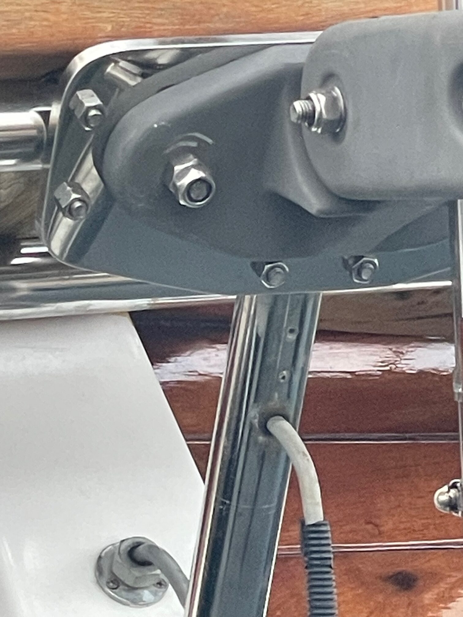
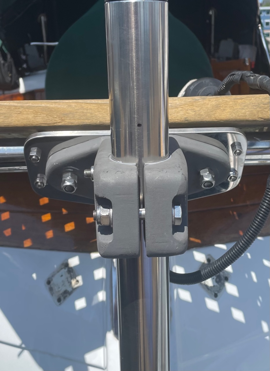
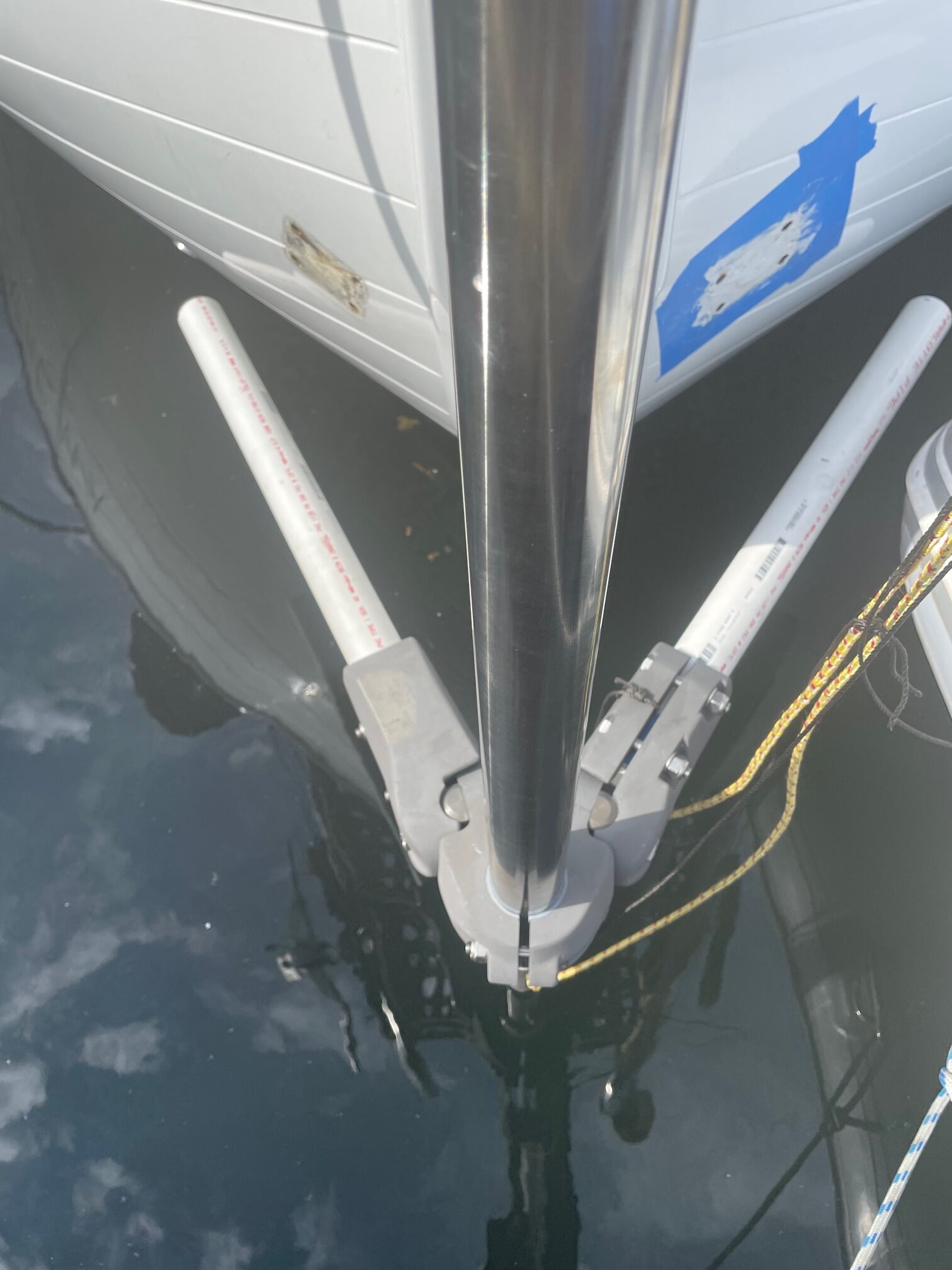
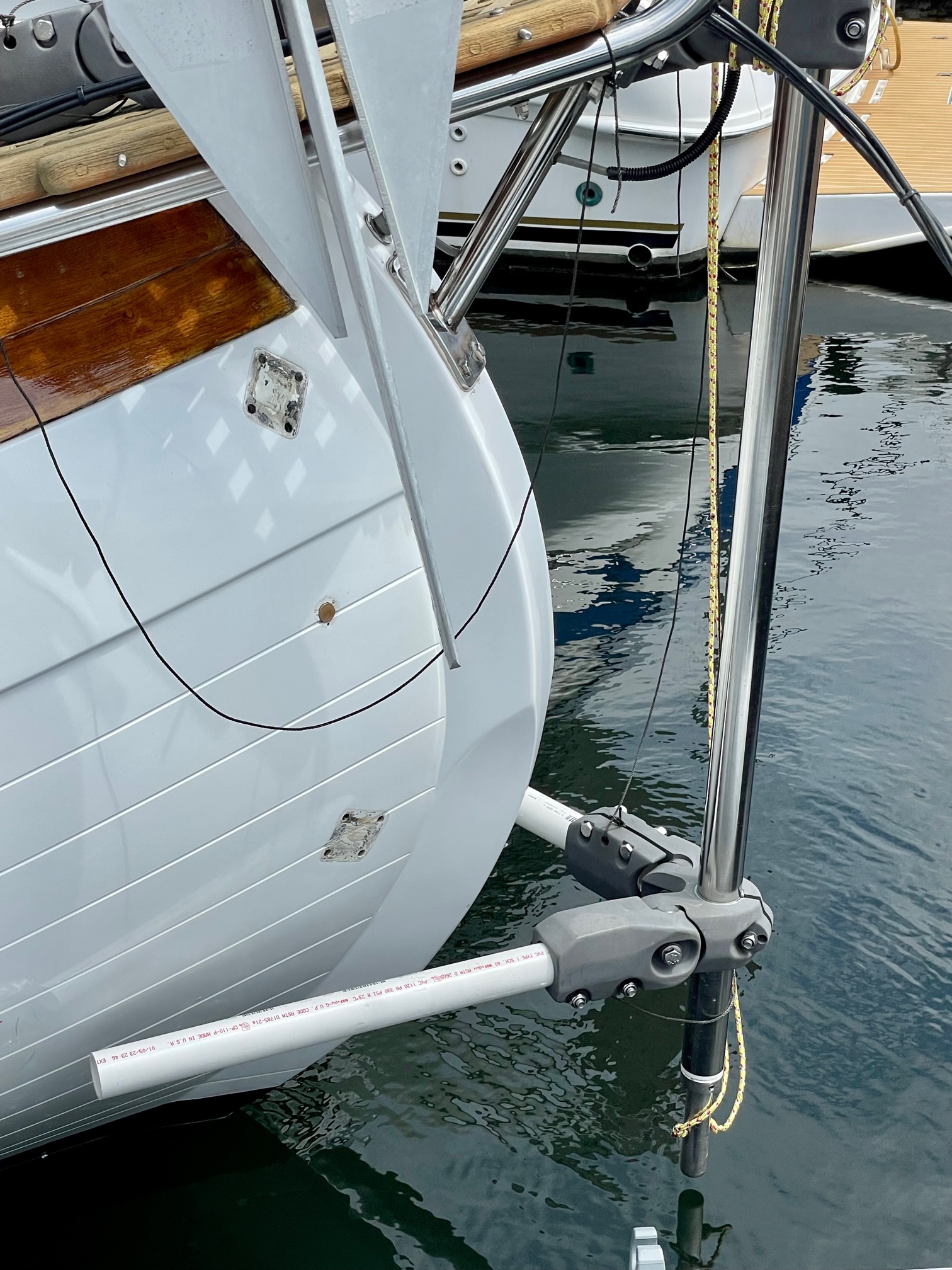
The increased size and weight of the new solar panels required a stronger mount. I built similar U-shaped frames out of 7/8″ stainless steel tubing as last time, but this time included an extra horizontal arm for better support. I also went from using a single strut to using 2 struts that support the frame to the hull. The frame attaches to 2 stanchions using spring pins, same as before. Two goals I had for the mount was to make the solar panels easily removable, and to make the panels adjustable. I decided on 3 settings– a 6 degree off horizontal, a 23 degree tilt away from the boat, and a 20 degree tilt toward the boat. This is accomplished by using 1″ thin walled tubing and 7/8″ thick walled tubing for the two struts. This allows the 7/8″ tubing to slide inside the 1″ tubing. The 23 degree tilt away from the boat is set by the length of the 7/8″ tubing (24″). The 6 degree horizontal position is accomplished by inserting a pin or bolt into a hole in each strut. Likewise, the 20 degree tilt towards the boat by inserting a pin into the 2nd hole in each strut. The panels can also be moved into an up position to get them out of the way during docking or going through locks.
6 degree23 degree-20 degree
The panel position is made easier to set with the addition of a line that is led from the panel, through a low friction ring lashed to a shroud, to a cleat on the dodger. I marked the line for the different panel positions. This makes it a 1-person job to change the panel angle or stow in the up-position.
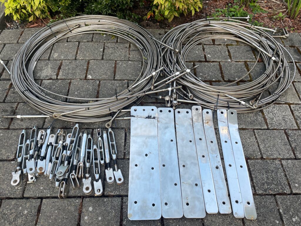
Standing rigging on boats should be replaced every 10-15 years, especially for boats taken offshore. The standing rigging on Apropos was 20 years old, so well past its due date for replacement. I decided to perform the job dockside and not pull the masts. This has its plusses and minuses. On the plus side, you can do all the work at the marina and don’t have haulout, mast crane, and yard fees. On the minus side, it takes a lot longer since you can only remove a certain number of shrouds/stays at a time in order to keep the masts from falling down. Apropos, being a ketch, has 2x the rigging and 2x the chainplates and since I planned on doing most of the work myself, I didn’t want to be in a boatyard for a month. There were also lots of variables like the time involved in getting new chainplates fabricated, sourcing custom chainplate bolts, and getting all the swaging work done. I also decided to make this as much of a DIY and learning project as possible. I hired a rigger (Terry from Yachtfitters) for guidance and technical expertise, but did most of the work myself.
Here are the main steps I followed for re-rigging Apropos:
Tune the rig to spec and mark all the shroud/stay turnbuckles with tape. This is needed to get the proper length for making the new shrouds/stays.
Remove groups of shrouds/stays strategically. For mizzen shrouds, brace the mast with temporary lines from masthead to deck. For main mast shrouds, remove in groups that allow adequate mast support from remaining shrouds. Deliver shrouds/stays to rigger, whose shop is a 2-minute walk from the marina.
Remove chainplates associated with the removed shrouds/stays and replace with new. Seal the gaps between chainplates and deck. Replace the chainplate bolts with new.
Pick up and install the new shrouds/stays from rigger, who did all the swaging work (attach the new wires to turnbuckes at deck end and eyes at mast end).
Repeat the previous 3 steps until done. I ended up splitting the entire re-rigging into 5 groups of shrouds/stays.
After all shrouds and stays have been replaced, re-tune the rig back to spec.
For cap shrouds, use seizing wire between spreader end and shroud to fix spreader angle. Add leather boots on spreader ends to protect the sails.
The remaining paragraphs provide details on some of the major parts of the project.
Going aloft
Re-rigging with masts in place requires lots of work aloft. In the past, I was never comfortable going aloft without another person spotting me and taking up slack in the backup/safety halyard. During the project, I probably made 20 trips up the masts. I learned from Terry (professional rigger) how to do it safely. I use a self-made 3:1 block and tackle connected to a climbing harness to go aloft. This allows me to pull myself up the mast with an effort of 1/3 my body weight. What I added to my climbing gear is a fall-arrest device that takes the place of a second safety halyard and the need for a 2nd person. The arrest device connects to my harness and slides up a halyard anchored to the deck. With this, every few feet after I pull myself up a with the 3:1, I slide the arrest device up above my head. If something fails on my main 3:1 halyard, the arrest device will keep me from falling. When I reach the mast level where I’m doing work, I make sure the arrest device is supporting my weight, then I tie off the lazy end of the 3:1 and can use both hands to remove/re-install tang bolts and cotter pins. When working alone, I also use a spare halyard to hoist the shrouds up the mast to the height of where they connect to instead of pulling them up with a messenger line. When removing shrouds/stays, I secure the spare halyard at the level of mast tang before going aloft, then I remove one shroud at a time and secure it to the spare halyard. I also bought a new canvas tool bag that I clip onto my harness that has a rigid top that keeps it open. This makes finding the right tool, tang pin, or cotter pin easier. There’s nothing worse than getting to the top of the mast and not having the correct tool, so I make sure I think everything through before going aloft and double check I have everything needed for the task. Since I made several trips up both mast heads, I took the opportunity to replace both topping lift lines.
From Mizzen Mast
Shrouds/Stays
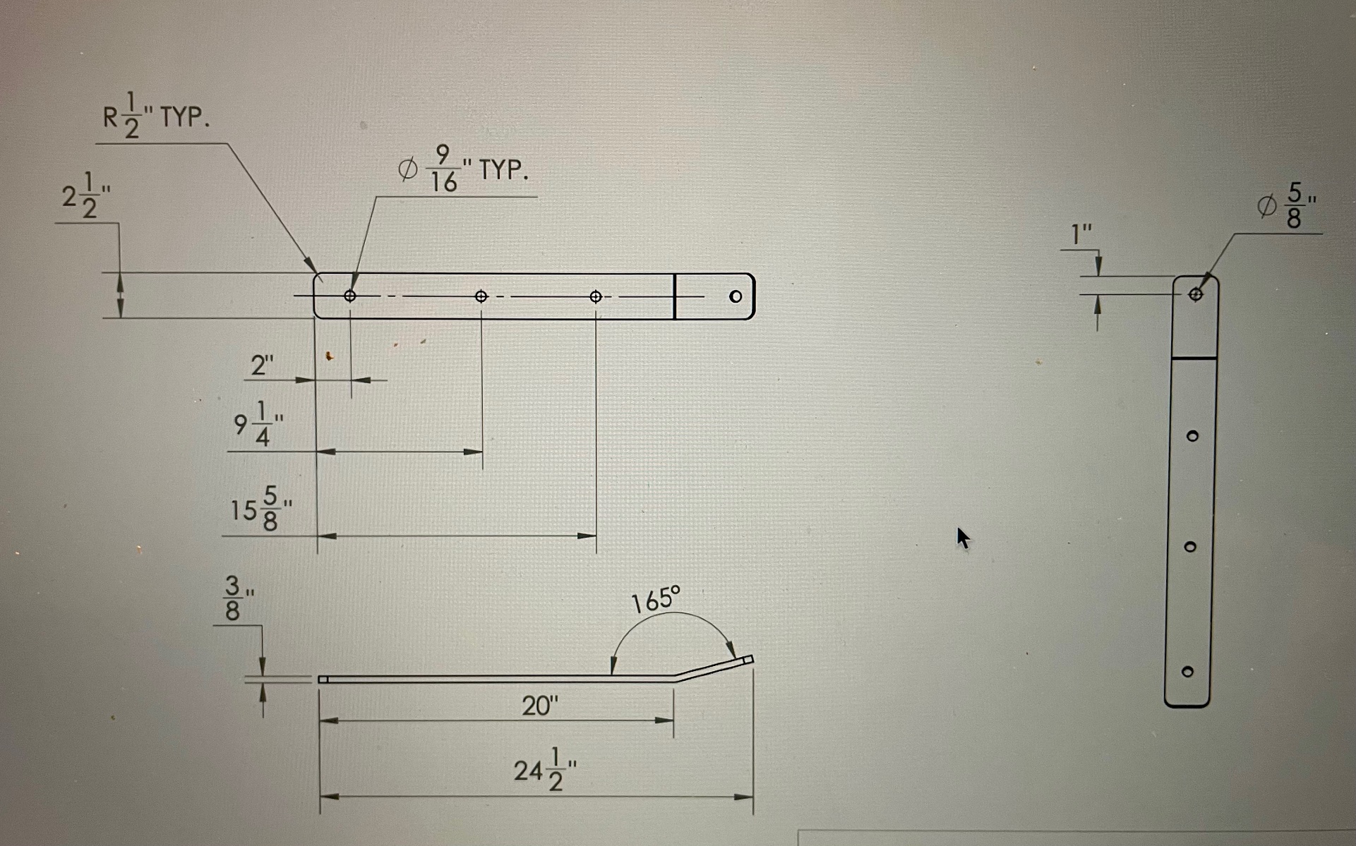
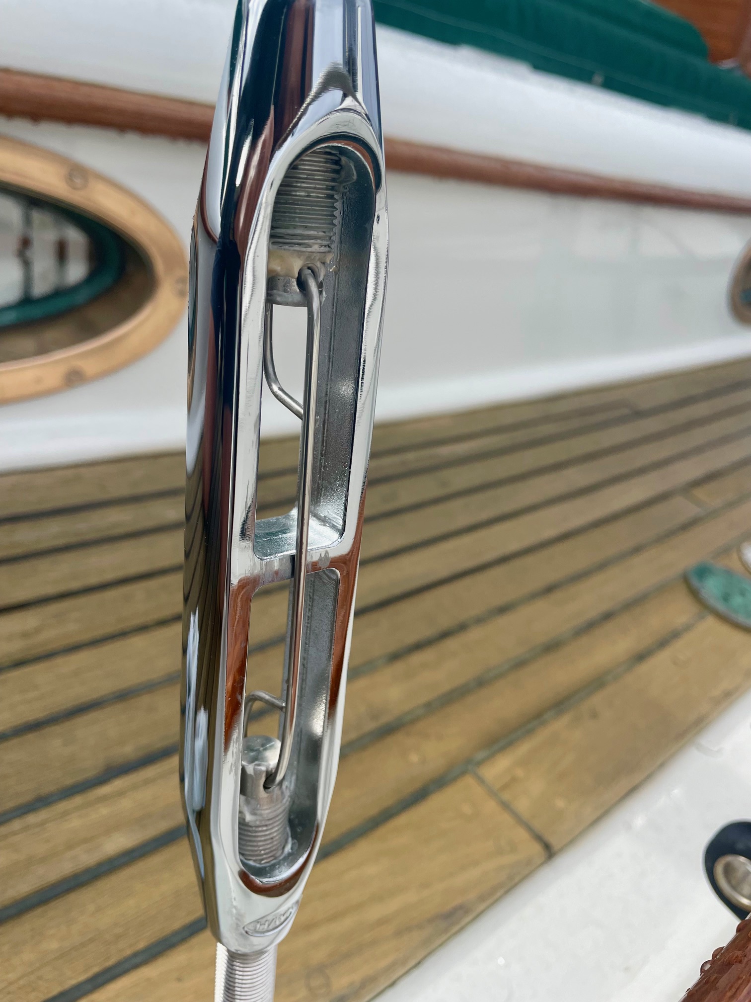
Apropos’ main mast is supported by 8 shrouds, 2 backstays, and 2 forestays. The mizzen mast is supported by 6 shrouds and a jumper stay. The bowsprit has 2 whisker stays and a bobstay. That’s a lot of rigging! All stays are 304 ss wire, with the exception of the bobstay which is solid 1″ ss rod. Most shrouds/stays are 3/8″, a few are 5/16″. All turnbuckles were replaced with high quality Hayn silicon bronze and tefgel was applied to the threads.
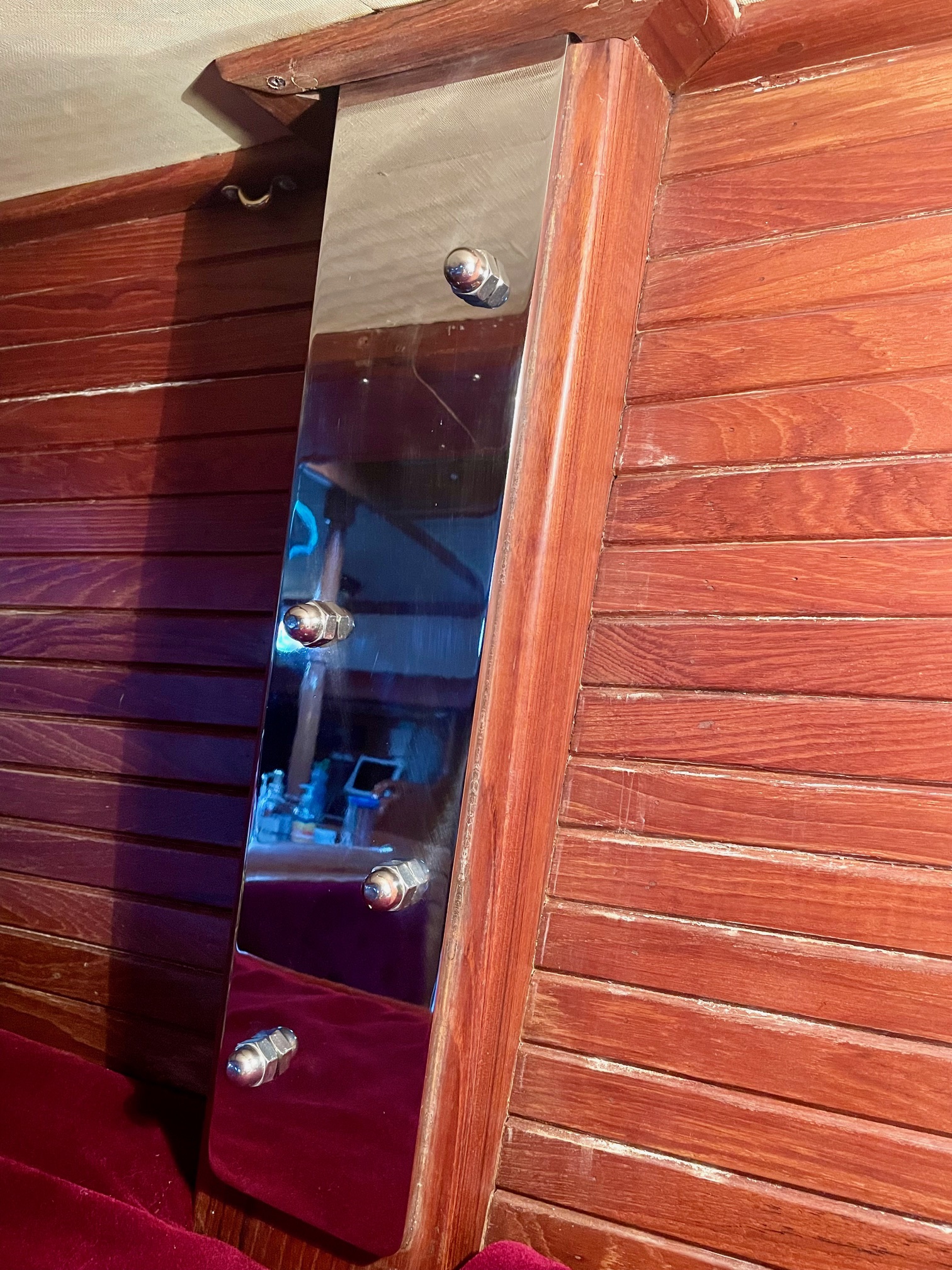
Chainplates
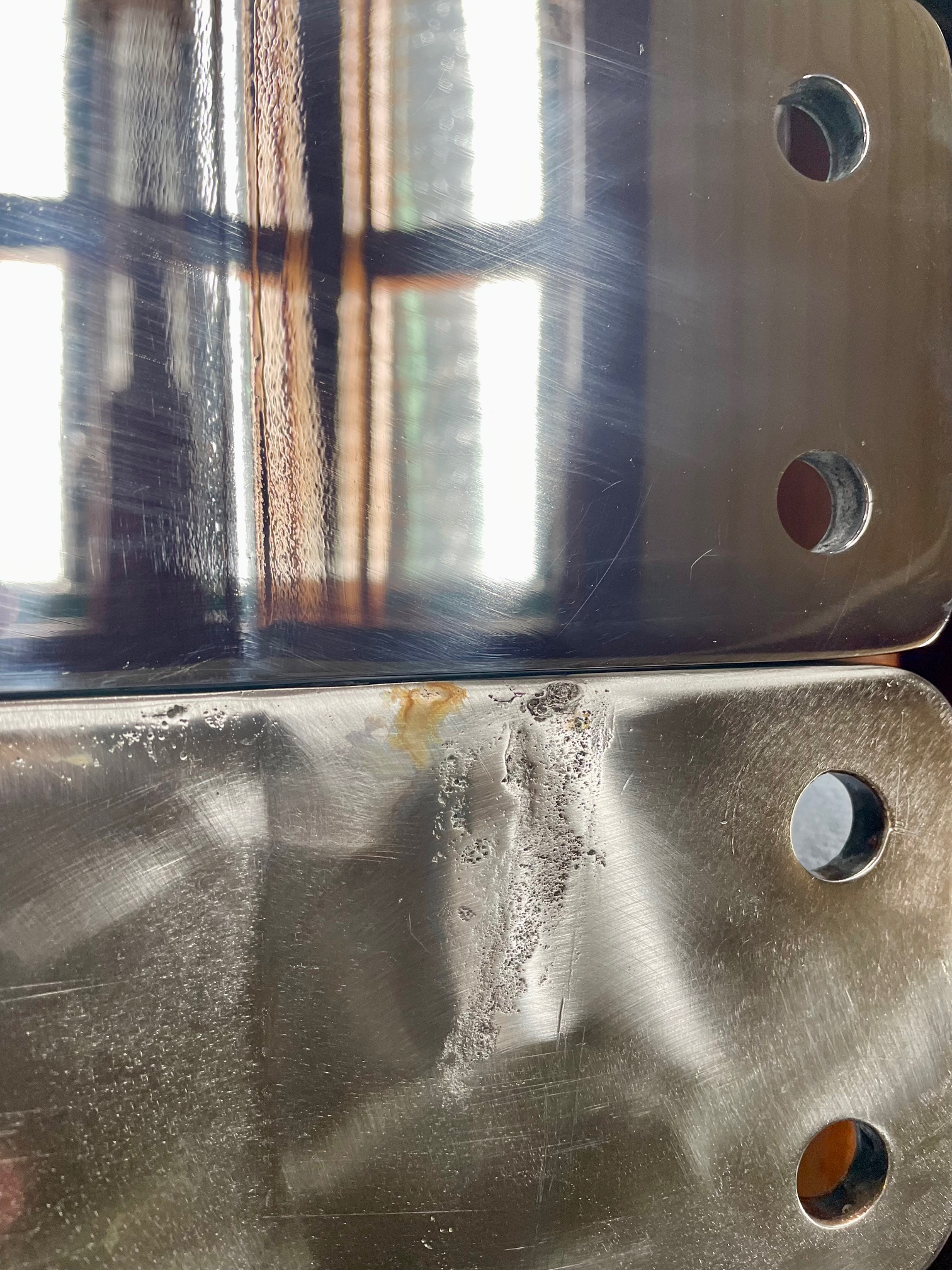
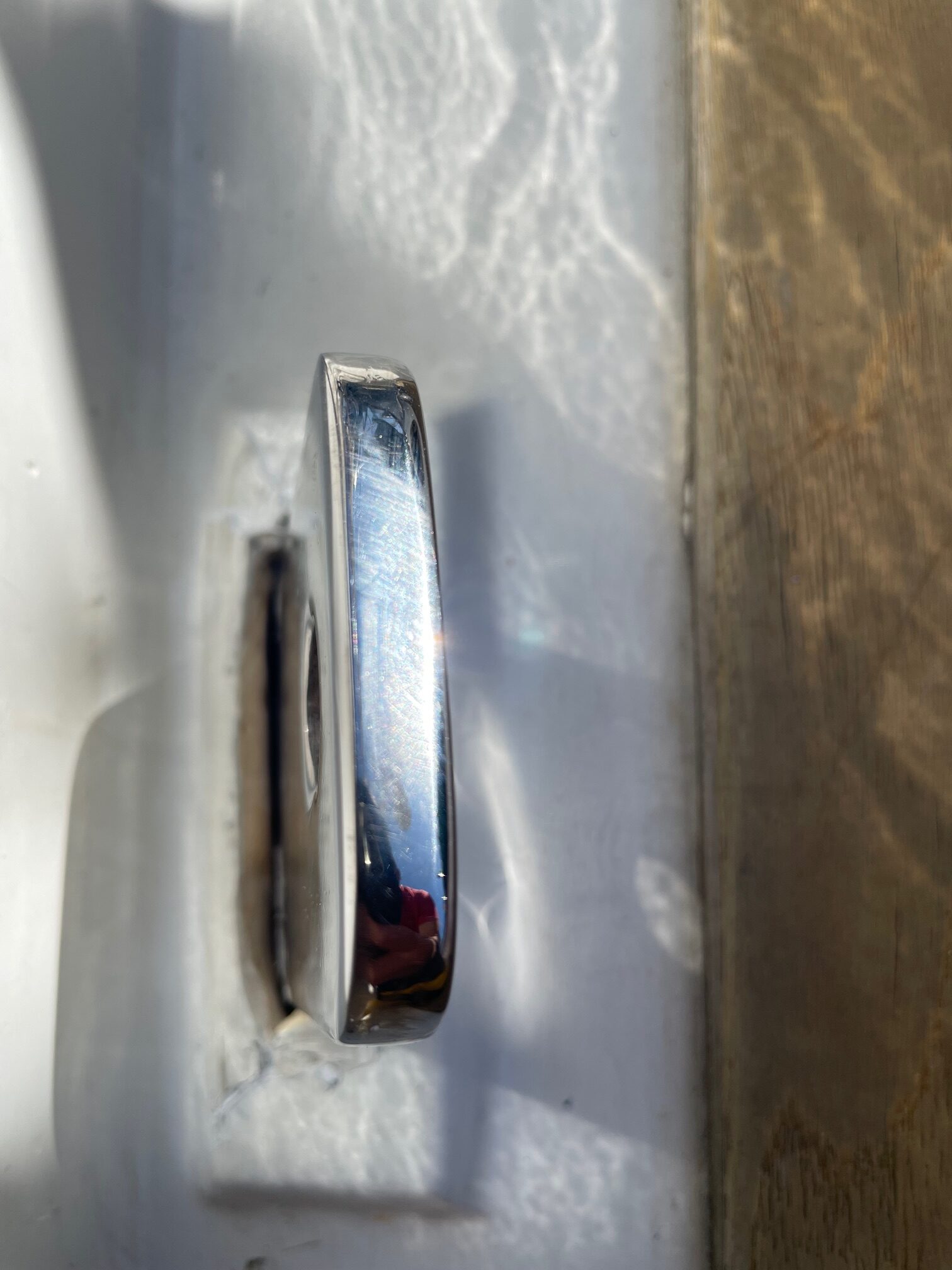
Chainplates secure the shrouds/stays securely to the boat at deck level. On Apropos, they are all internal, which means they go through the deck and bolt on to teak timbers inside the cabin. Even though they are 3/8″ thick 316 stainless steel, crevice corrosion usually occurs in the area between the deck and the opening down below. It’s usually a combination of salt water intrusion and lack of oxygen that causes the corrosion. All the chainplates on Apropos were original, which makes them 42 years old. I had no idea what condition they were in, so I planned to remove all of them to inspect & replace.
Removing
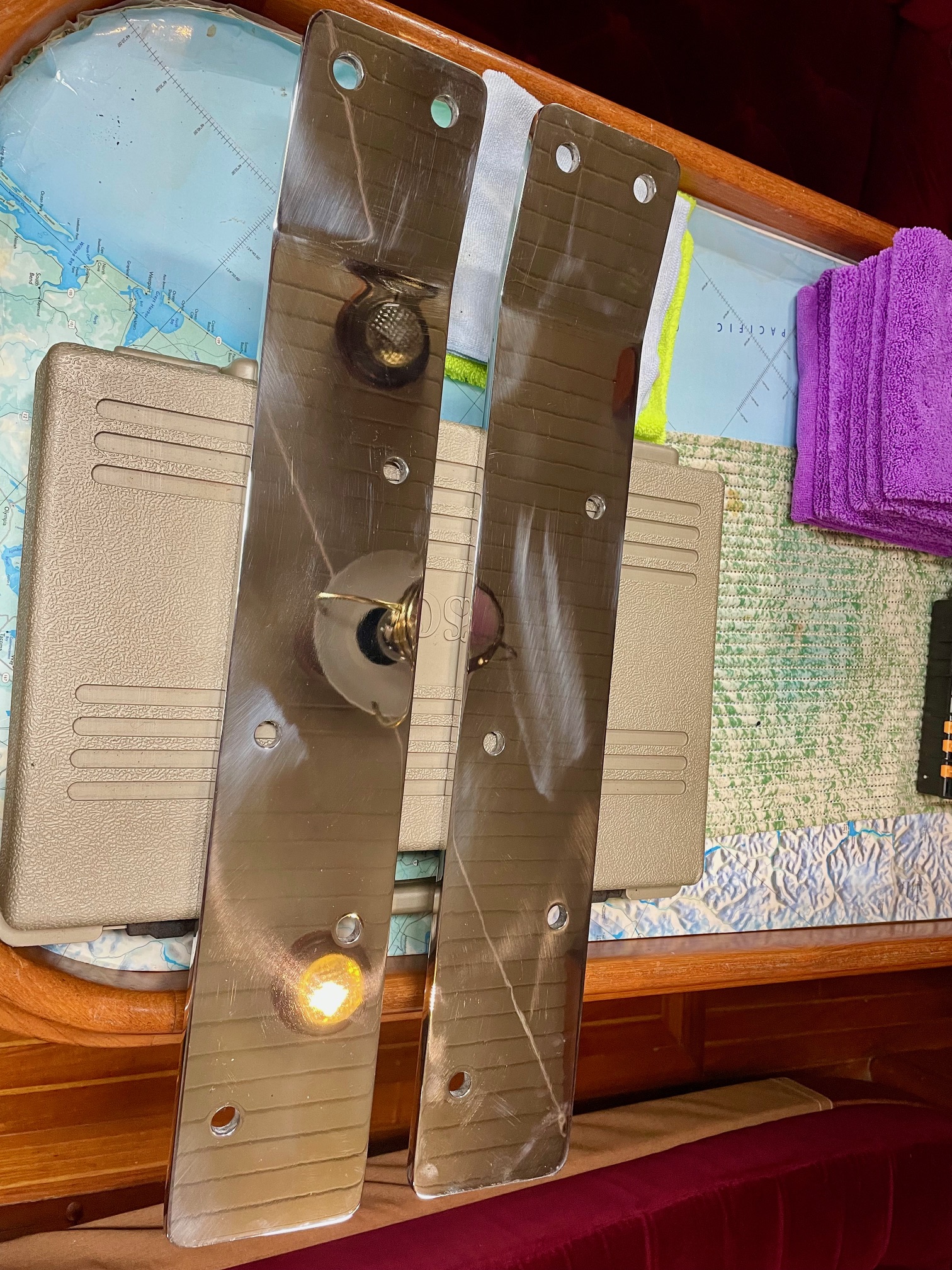
Removing the 10 chainplates was no easy task. There are 2 triples (for 3 shrouds) that are 6.5″ wide, 2 doubles (for 2 shrouds) that are 4.25″ wide, and 6 singles (for 1 shroud) that are 2.5″ wide. Each chainplate has an approximately 166 degree bend, which is the angle between the hull sides and the shrouds. Because the bend is inside the core, the chainplates need to be removed downwards, often with a lot of force. I used blocks of wood and a heavy mallet to pound them down from above. The triples were by far the most difficult to remove and the wood blocks kept splitting, so I made a 2.5″ x 2.5″ x 12″ piece of UHMW polyethylene with a 3/8″ notch routed on the bottom to help pound the chainplates down. Because of the bend in the chainplates, removing them caused the outboard edge of the raised deck piece to break off. After re-installing the new chainplates, I used thickened epoxy to reattach them.
Fabricating
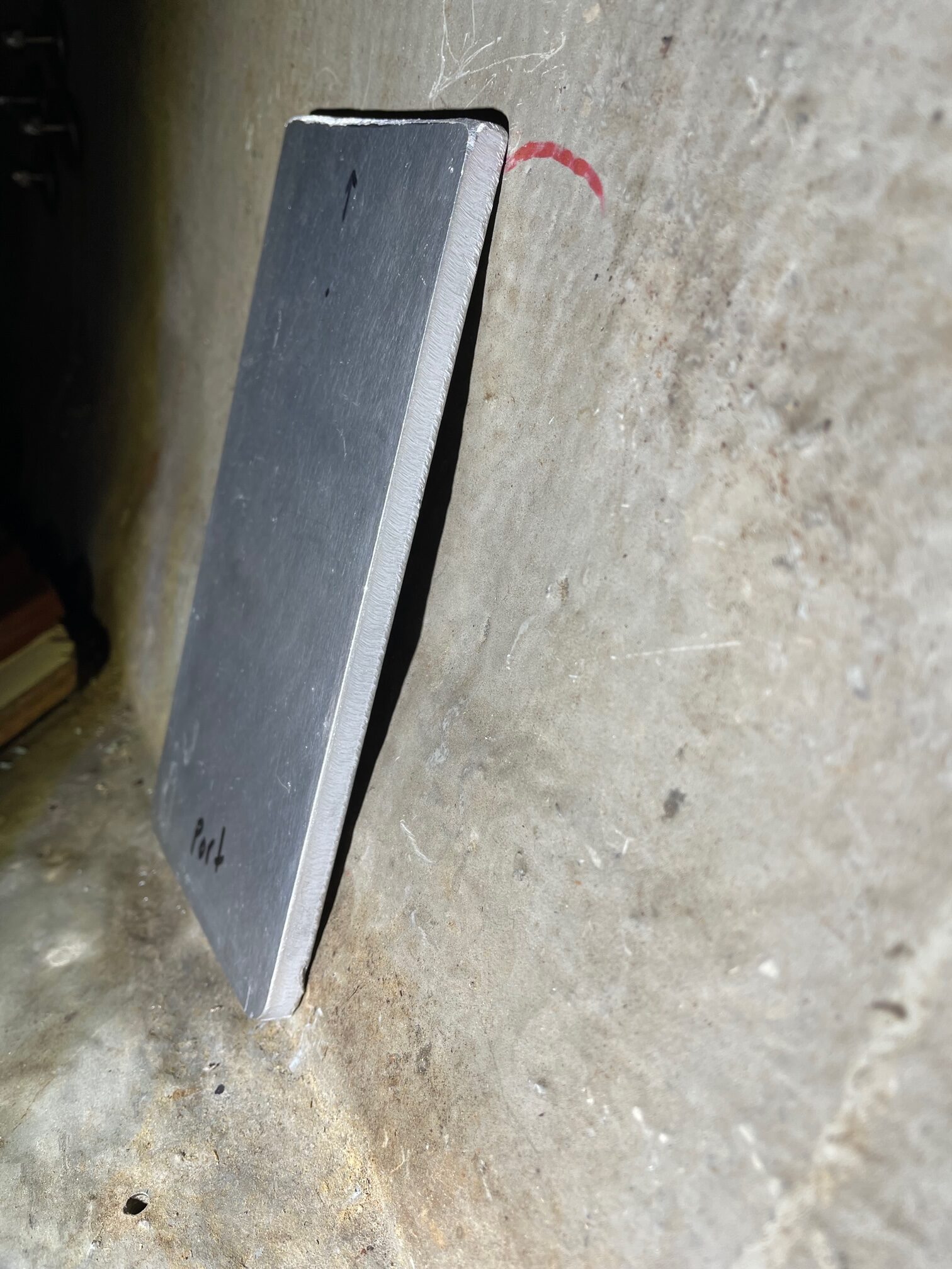
Garhauer Marine fabricated and mirror-polished the new chainplates from 316 stainless steel. They have reasonable prices and great customer service. I supplied them with detailed drawings and they all fit perfectly.
New ChainplatesOld Chainplate Showing Crevice Corrosion
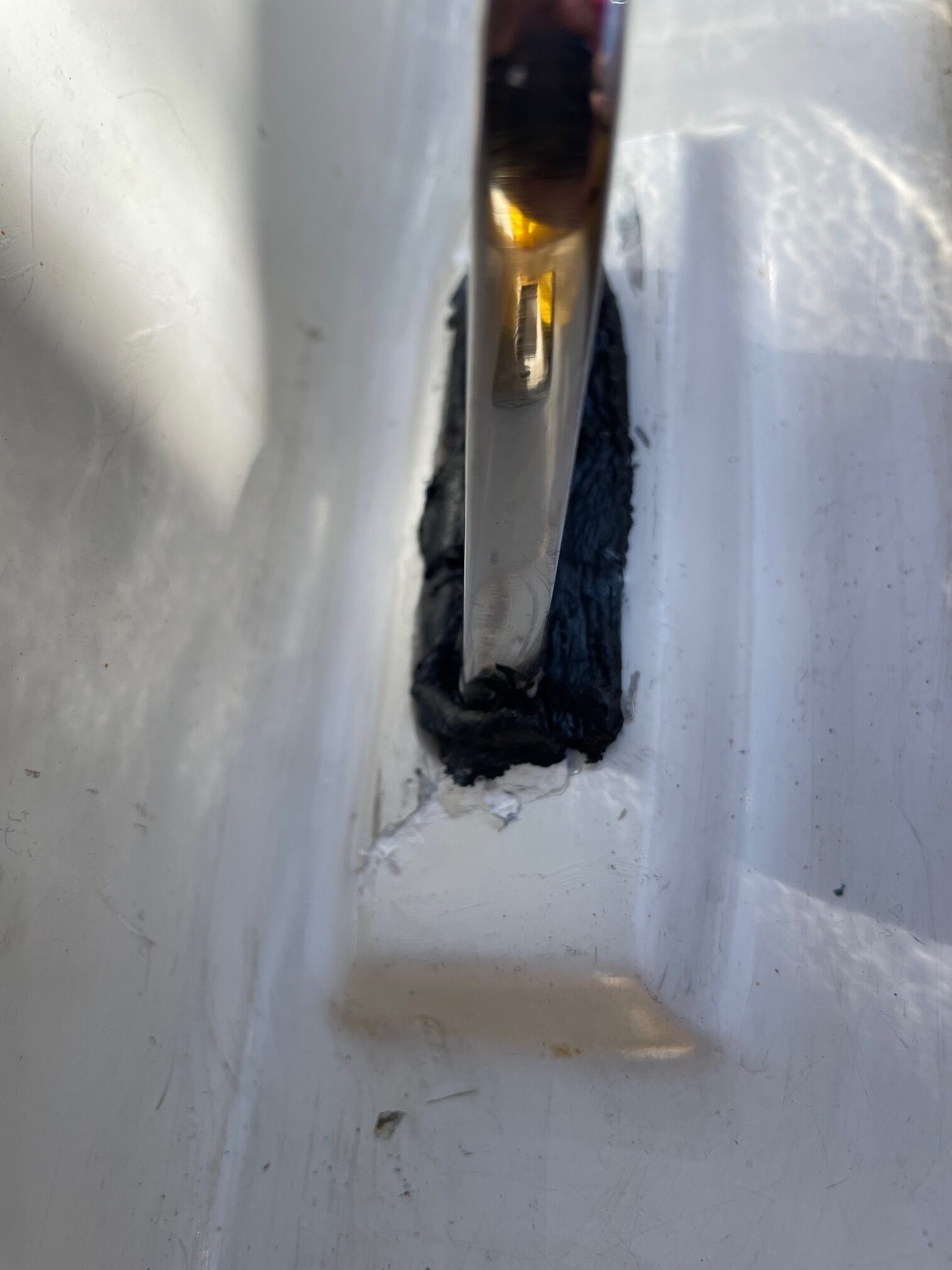
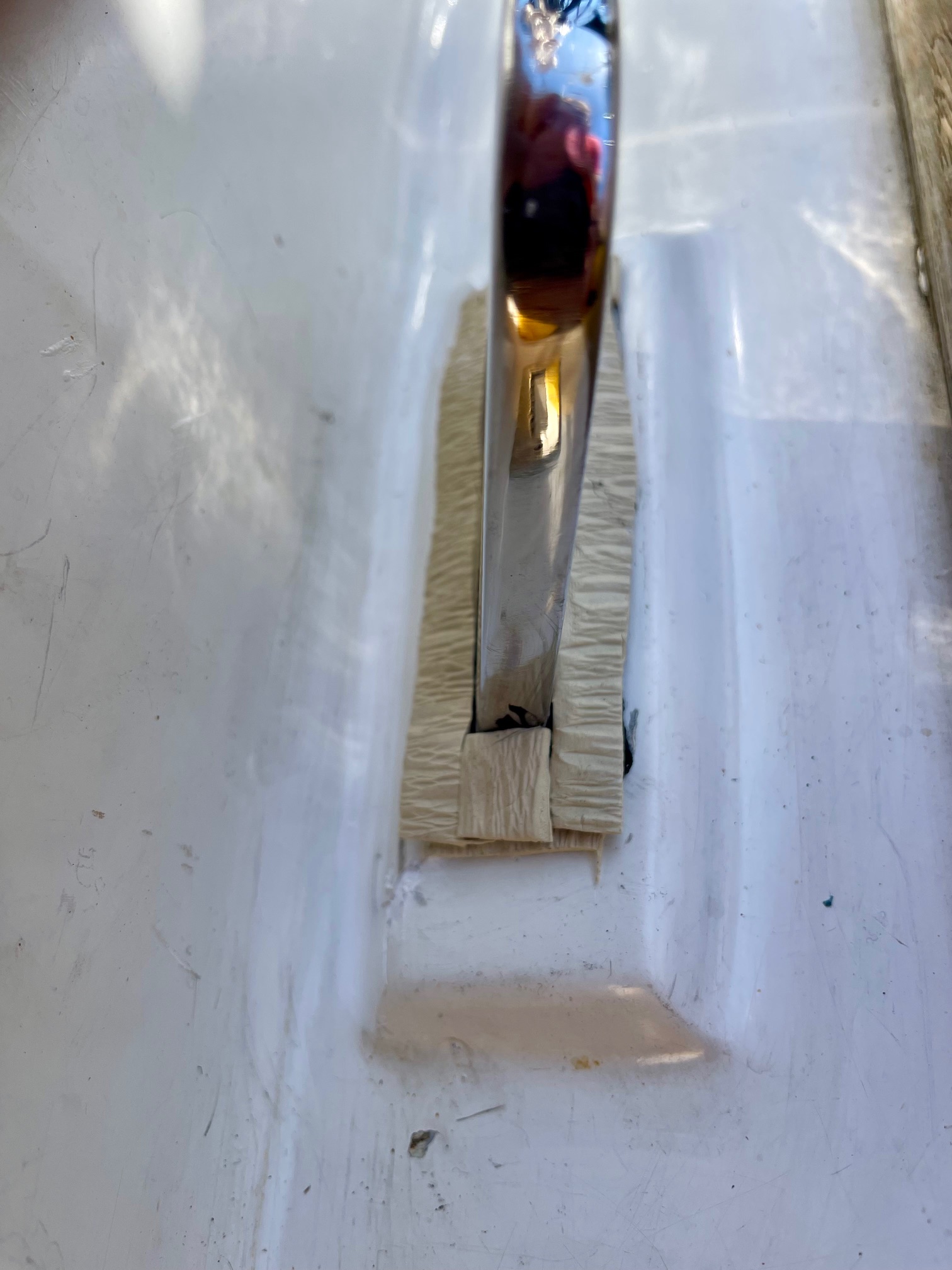
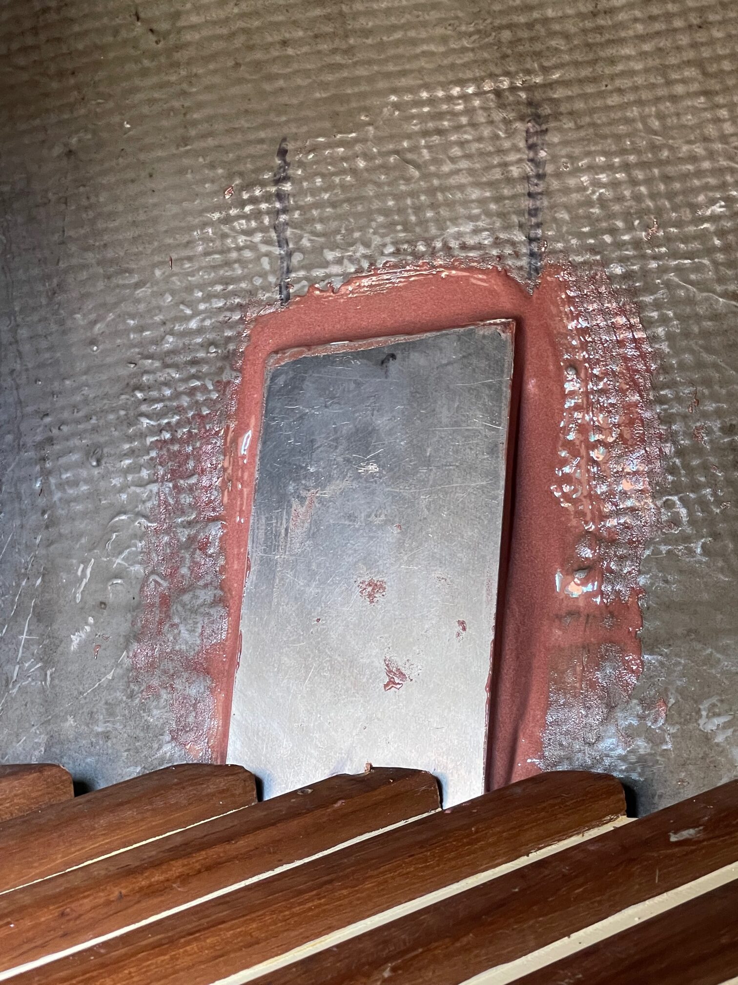
Sealing
It’s important to have a good water-tight seal around the chainplates at deck level. I like to do the sealing before attaching the shrouds for easier access. Here are the steps I followed:
Clean the area around the chainplate with acetone
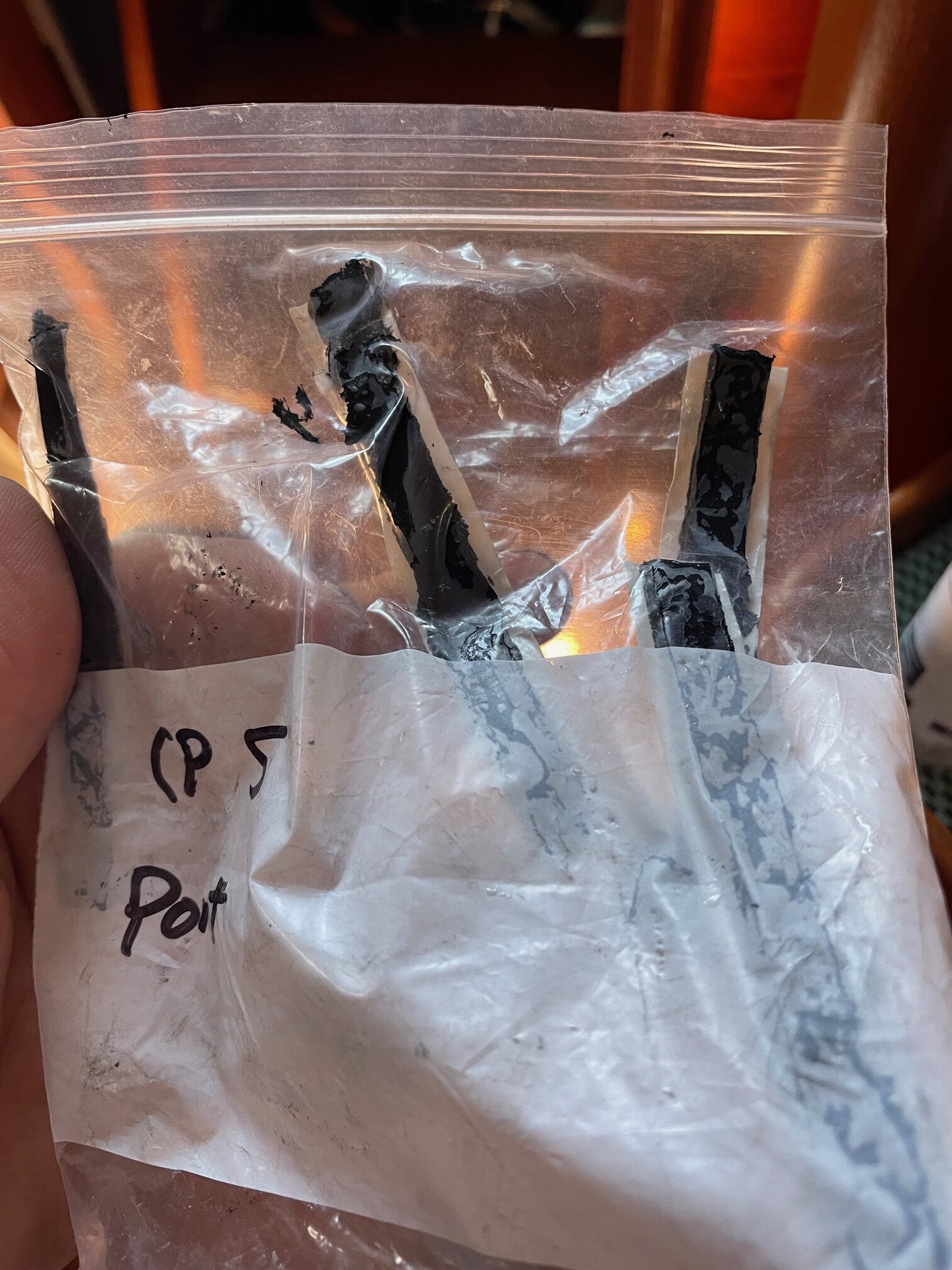
Apply black butyl rubber (McMaster-Carr #75875A661) along both sides of the chainplate and at both ends. The black butyl is extremely tacky, so put pre-cut strips inside a ziplock back and place it in the refrigerator for 15 minutes. It’s best to leave the paper strip on, then push it into the gaps between the chainplate and deck and then peal off the paper.
Apply white butyl (clay-like, non hardening McMaster-Carr #9408T146) overtop the black, along both sides and at both ends. Since the white butyl doesn’t stick to your fingers, use it to push more of the black butyl into the gap. On colder days I like to use a heat gun to warm the chainplate and butyl slightly.
Fasten the stainless steel cover plate and secure with 2 ss screws. It helps to push down on the cover plate as screws are being tightened. A little heat can also help to compress things and get a good seal. The plate will not be flush against the deck, it will be raised slightly because of the white butyl. Trim off any butyl as necessary.
This process should give a watertight seal. So far none of the 10 chainplates have leaked.
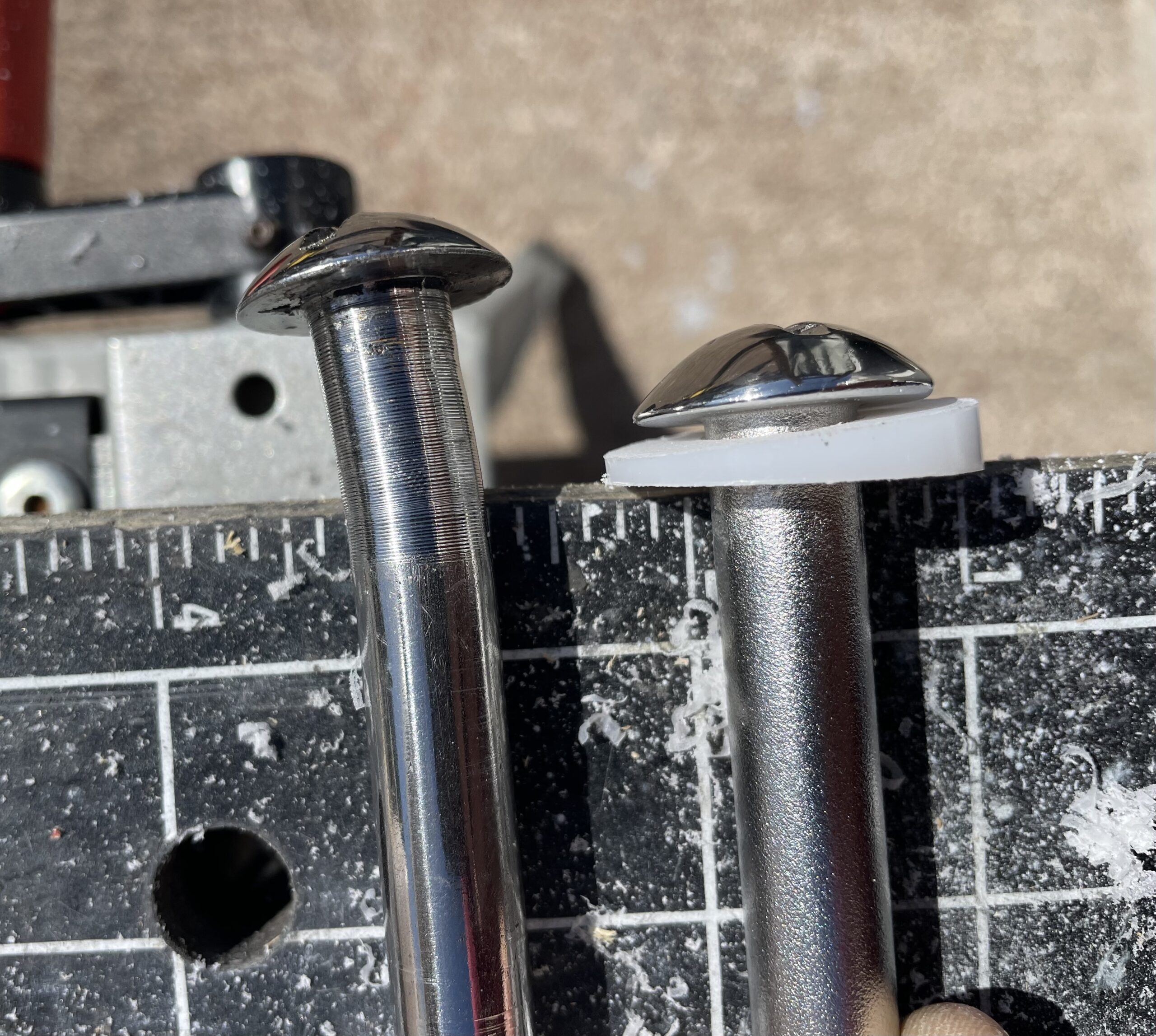
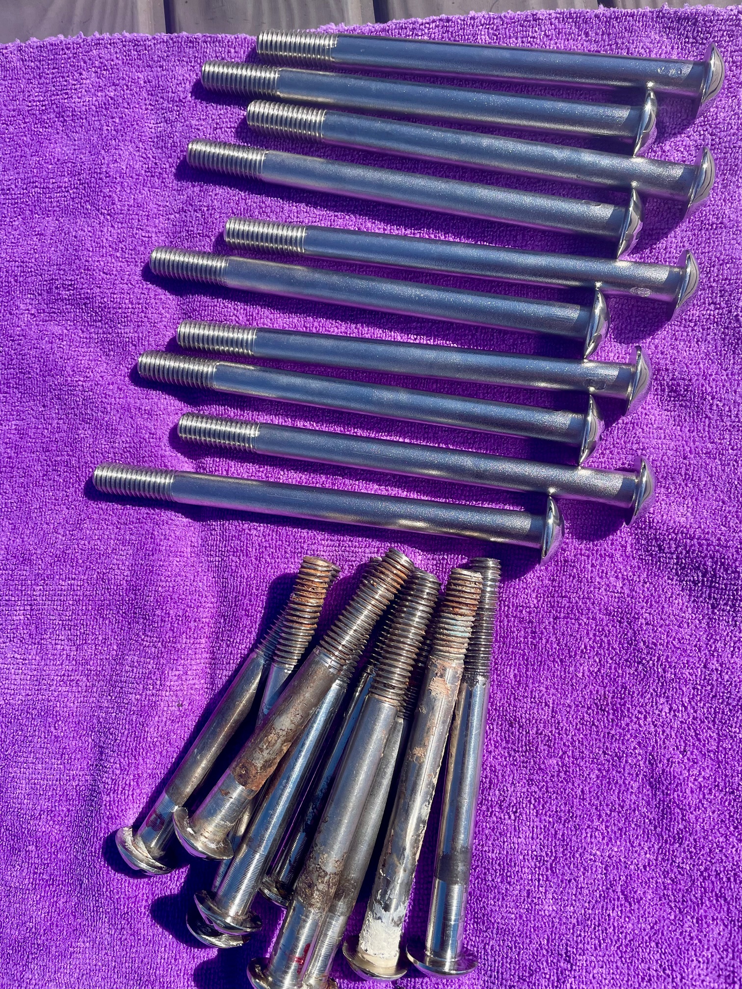
Bolts
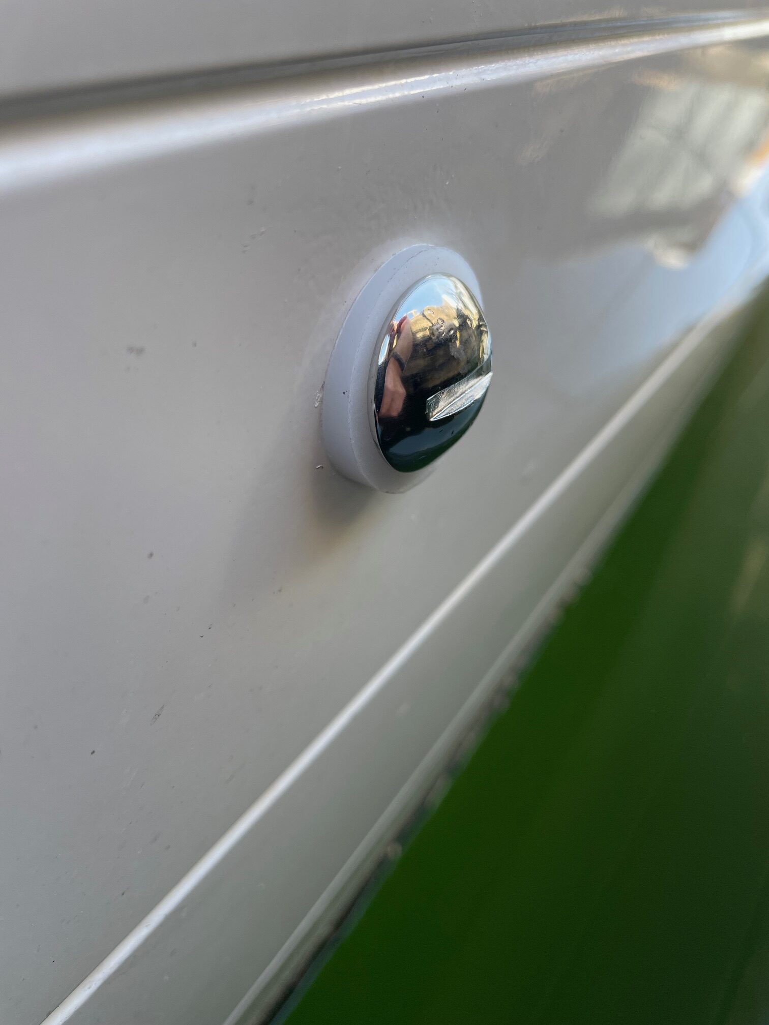
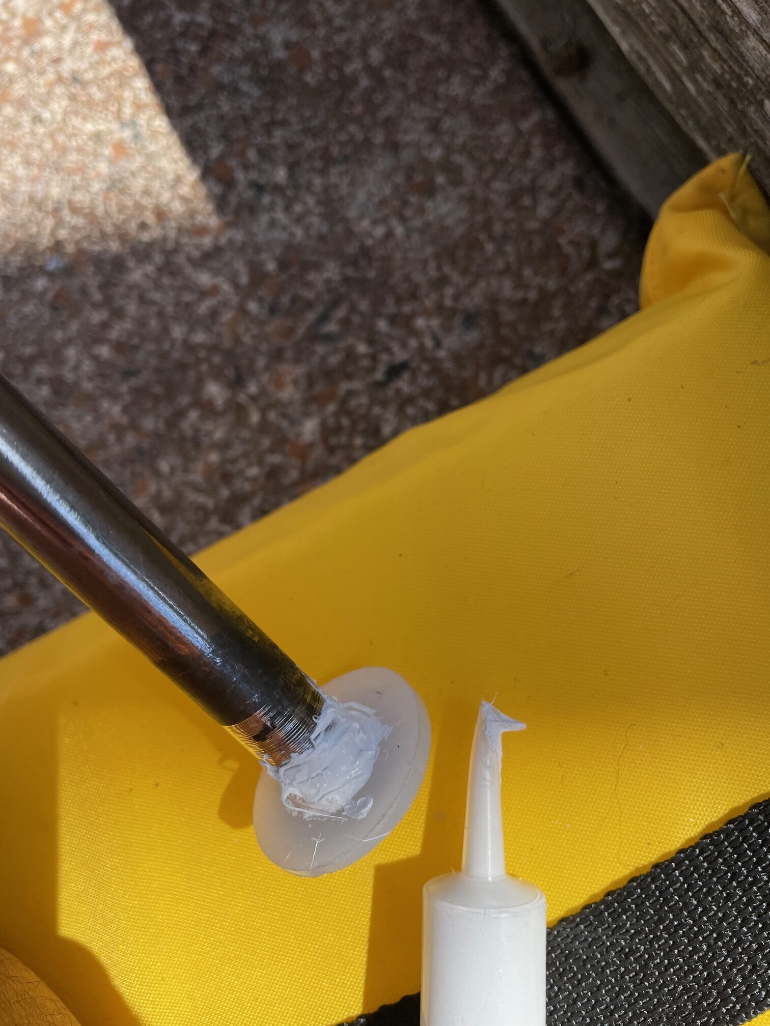
Most of the 36 bolts that secure the chainplates to the hull showed signs of corrosion. I replaced them with new custom made 316 stainless steel 1/2″ bolts. The new bolts started out as carriage bolts and were machined to remove the square under the head, then a slot was milled into the head and threads were cut. Since the bolts came from stock, I polished the heads to a mirror finish. I ordered 2 sizes, 6-3/4″ and 5-5/8″ lengths, both with 1-1/2″ of threads. With these 2 lengths I was able to custom fit each one by cutting the length with an angle grinder. The heads on the original 16 bolts for the 4 stern chainplates were bent to account for the angle difference of the hull and bolt . Instead of trying to bend the heads of the new bolts, I decided to make custom tapered washers. I bought a 2 foot long tube of Tivar UHMW polyethylene 1-1/4″OD, 5/8″ ID (McMaster-Carr #8705K91) and used a chop saw to cut the washers. Each one had to be custom fit with taper angles between 3 and 10 degrees.
Old bolt (left) with bend, new bolt (right)New bolt with tapered washer
When installing the bolts, I used a bead of white Sikaflex 291 marine sealant between the washer and hull. I aligned each bolt orientation with the slot horizontal.
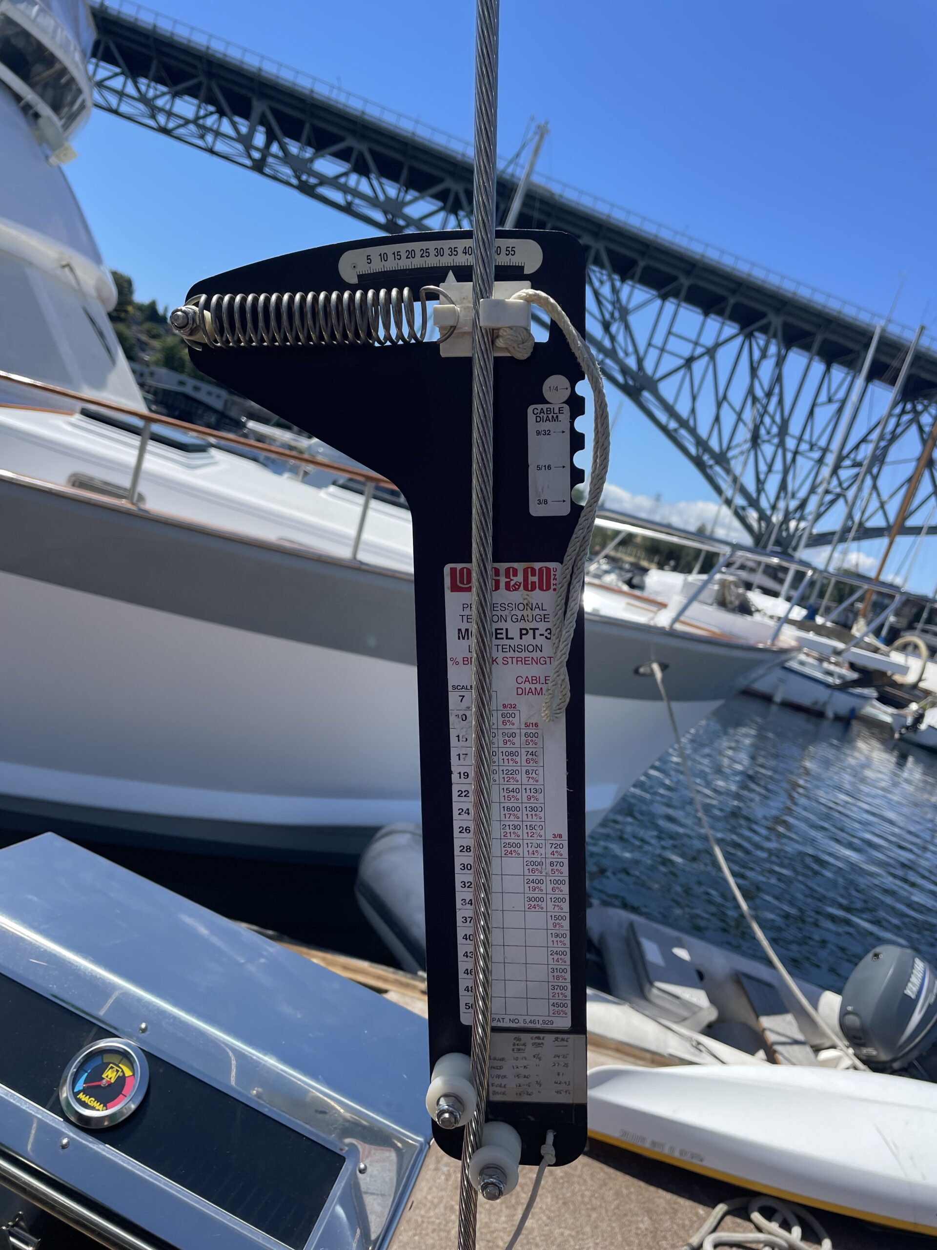
Final Rig Tuning
Rig tuning is done by adjusting turnbuckles to get the proper tension on the shrouds/stays. A good rigger knows the proper tensions for each particular shroud/stay–cap shrouds, backstays, fore-stays, intermediates, and lowers. A tension gauge (Loos & Co. Model PT-3) is used to measure wire tension. It works by measuring the deflection along a 12″ section of the wire with a spring. As the wire tension is increased, the readout (scale from 0 to 60) goes up. A convenient table printed on the gauge is used to convert the scale to lbs tension and % break strength. In the picture below, the readout is 34 on 3/8″ wire, so the lbs tension is 1200 and the % break strength is 7.
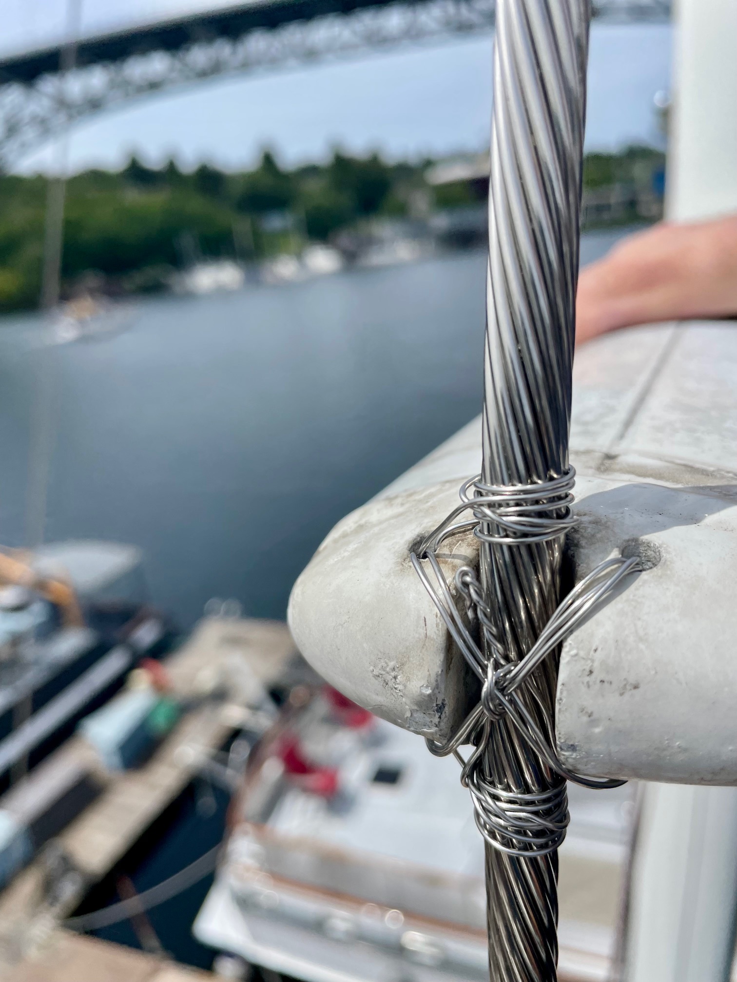
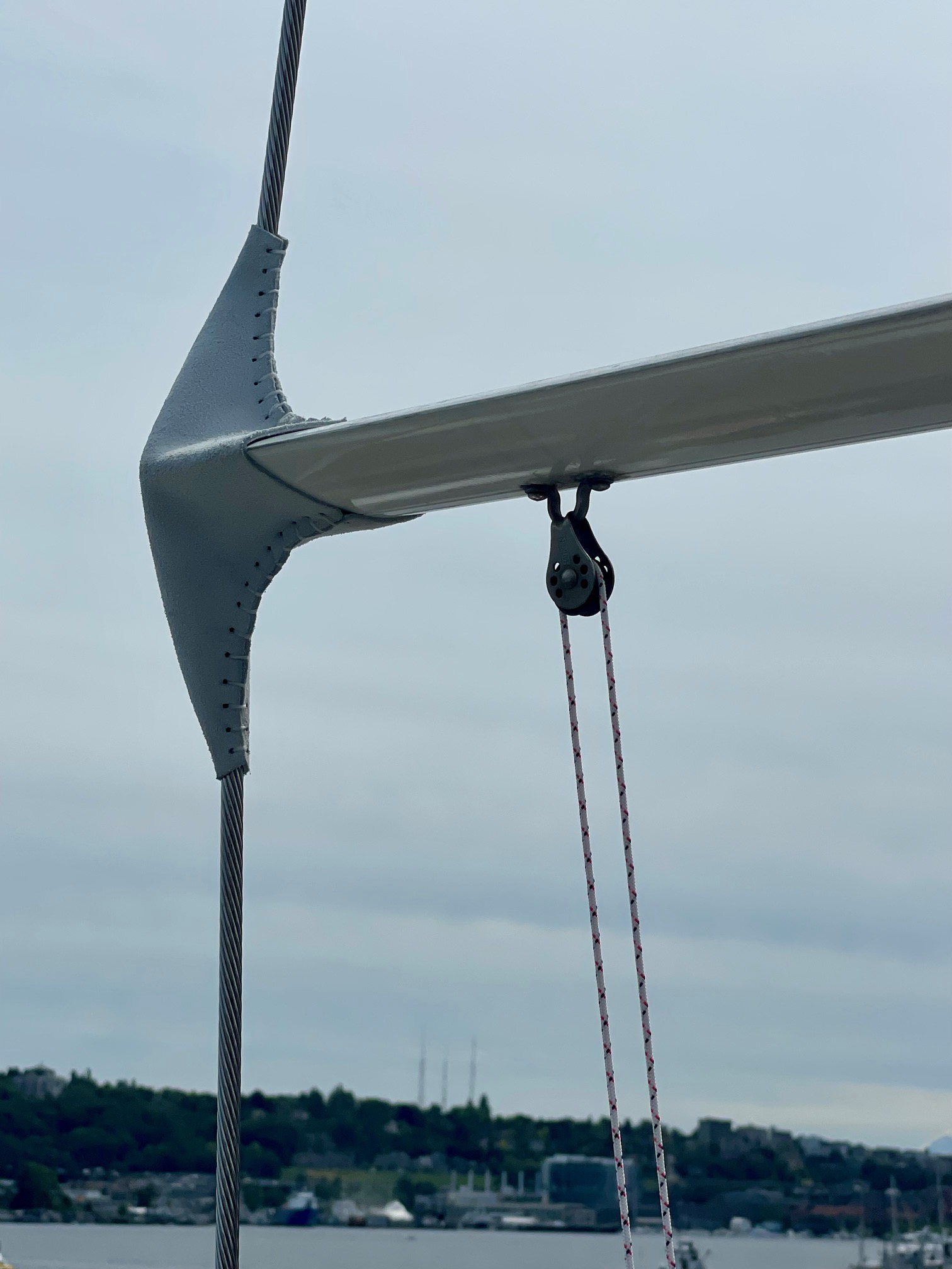
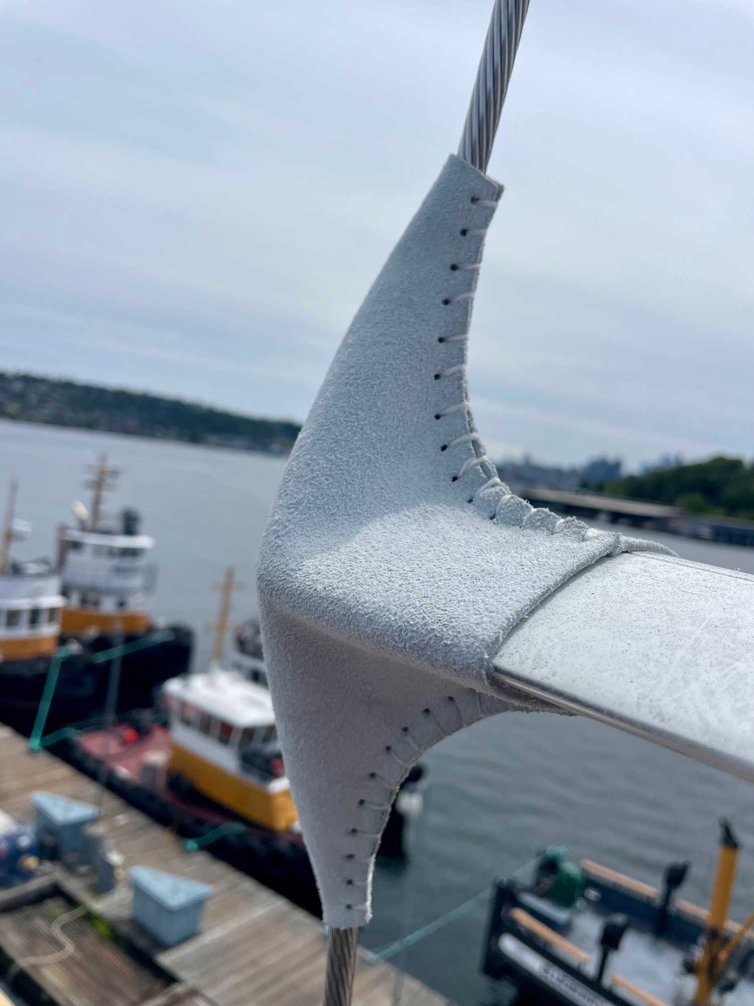
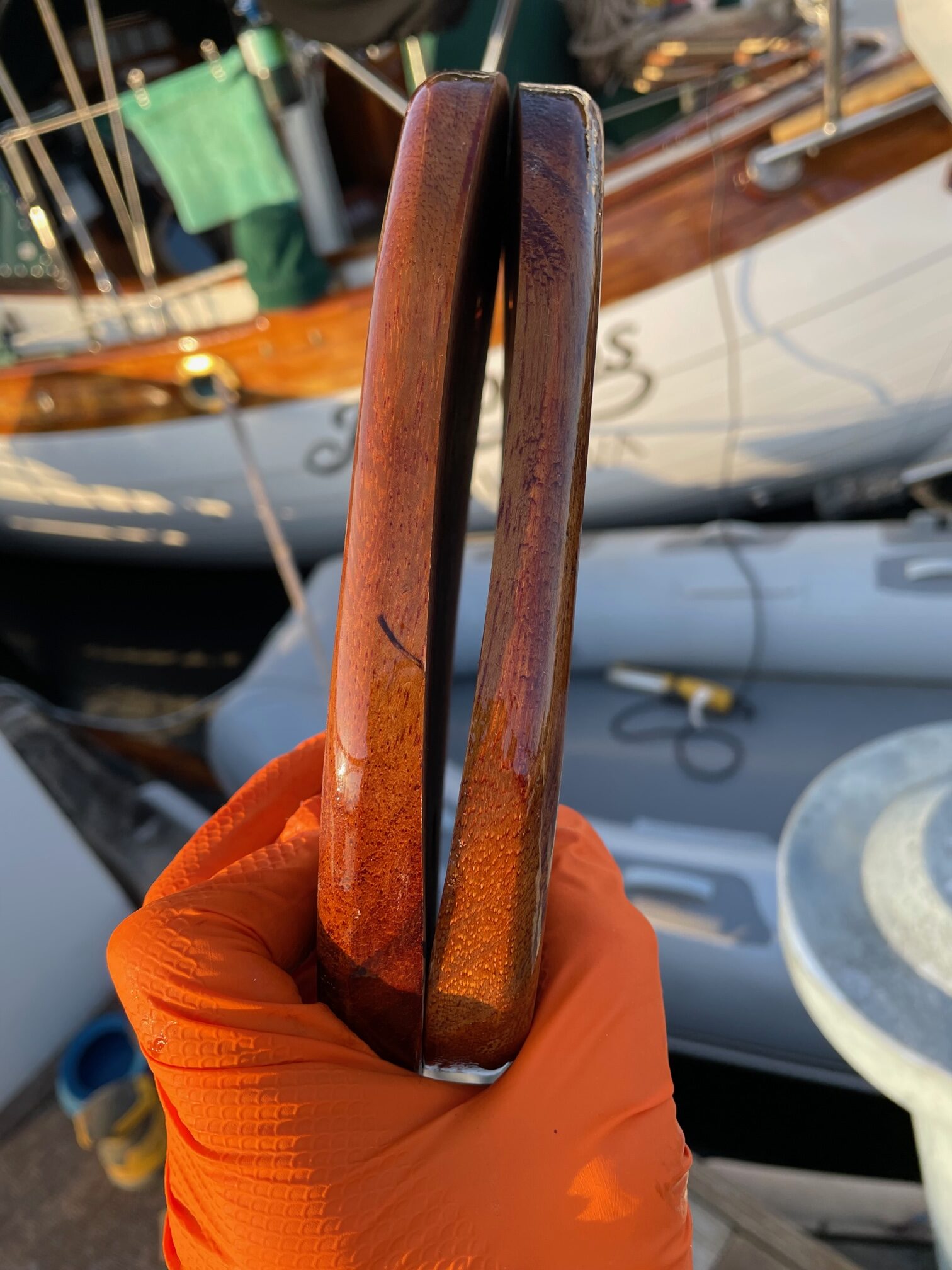
There’s another component to rig tuning besides using a tension gauge and adjusting turnbuckles. An experienced rigger constantly monitors the mast for shape. This is done by sighting up the mast from all 4 sides. The art comes in by knowing which shroud/stay to adjust to produce the intended change in the mast bend. It’s also important to get the spreader angles even. This can be done by measuring from each spreader tip to the deck. Each spreader can be bumped up/down until port and starboard tips are equal distance to the deck. Next stainless steel wire is used to seize the shroud at the spreader tip, which locks the spreader angle in place. The final step is to place spreader boots on the tips to protect the sail when it comes in contact with the spreader. I decided to use leather boots instead of the rubber type that was on the boat before. The leather boots need to be stitched on using a herring-bone stitch, which took about 30 minutes each. Instead of a climbing harness, I used a bosun chair which is way more comfortable for the 2 hours it took to stitch on 4 spreader boots.
Pinning the turnbuckles is typically done with cotter pins. Another method is using stainless steel welding rod. This gives a cleaner look and prevents snagging lines.
Here are the wire sizes and specs for the final rig tuning:
Main mast cap shroud 3/8″ wire, 44 or 15%
Main mast fwd lower 3/8″ wire, 42 or 13%
Main mast aft lower 3/8″ wire, 38 or 10%
Main mast intermediate 5/16″ wire, 23.5 or 10.5%
Main mast backstays 3/8″ wire, 34 or 7%
Main mast inner forestay 3/8″ wire, 35.5 or 8%
Main mast headstay 3/8″ wire
Mizzen mast fwd 3/8″ wire, 41 or 12%
Mizzen mast lower 5/16″ wire, 21 or 8.5%
Mizzen mast cap shroud 5/16″ wire, 26 or 12%
Mizzen mast jumper stay 1/4″ wire, 7 or 5%
Bowsprit whisker stays 3/8″ wire, 38 or 10%
Conclusion
The project took about 2 months from start to end. It involved a lot of custom fabrication, plenty of trips up & down the masts, and hours working aloft. It was a good learning experience and something I shouldn’t have to repeat again on Apropos. Replacing the standing rigging and chainplates will give me some peace of mind when sailing offshore in heavy weather conditions.
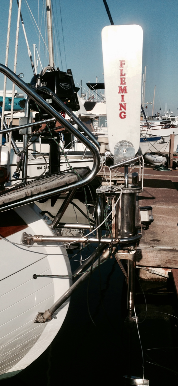
Apropos came with a Fleming Servo-Pendulum windvane. It was an older version (1980’s) and heavily built of stainless steel. I mounted it on the stern with existing hardware and eventually learned how to use it. A servo-pendulum system steers the boat relative to the wind by deflecting a vane that pivots a paddle in the water. As it pivots, the water pressure swings the paddle in a pendulum motion, moving lines running from the windvane to a drum attached to the wheel. This turns the wheel and hence the boat rudder. We sailed thousands of ocean miles with “Ian” doing the majority of the steering. As with any windvane, having a balanced boat is the most important thing.
Here are some of the problems we encountered with Ian.
The path the control lines take from the windvane to the wheel are through the hull into the lazerette, into the cockpit, and to a drum attached to the wheel. Three sets of blocks were used along the way but there was still a lot of friction. Enough apparent wind was needed to overcome the friction to make it work. On long ocean passages, this wasn’t too much of an issue. But chafing of the control lines and getting the proper tension on the lines were constant struggles.
Wear and tear on the boat’s steering system was another concern. In action, a servo pendulum system is constantly turning the wheel back and forth by small amounts for course correction. Even though the rudder is only moving by small amounts and the boat is sailing relatively straight, there’s constant movement of the steering system.
An unexpected mishap occurred during an offshore passage from Kiribati to Hawaii, when a weld joint on the paddle failed and the paddle sunk to the bottom of the ocean. We were 8 days into a 10 day passage, so we hand-steered the rest of the way. Even though Fleming is no longer making windvanes, they still had parts and I was able to have a new paddle shipped to Hawaii and had it welded back onto the shaft. It worked on a windy 20 day passage from Hawaii to Seattle. But the point is, 35-year old equipment is bound to have problems and I didn’t trust it anymore.
The vane adjustment was difficult to use. It has a ratcheting 360 degree vane with 120 teeth to provide 3 deg adjustment. I extended 2 lines as toggles so you didn’t have to reach all the way back to the windvane to adjust it, but it was still a bit clunky to use.
Old Fleming Windvane (“Ian”)
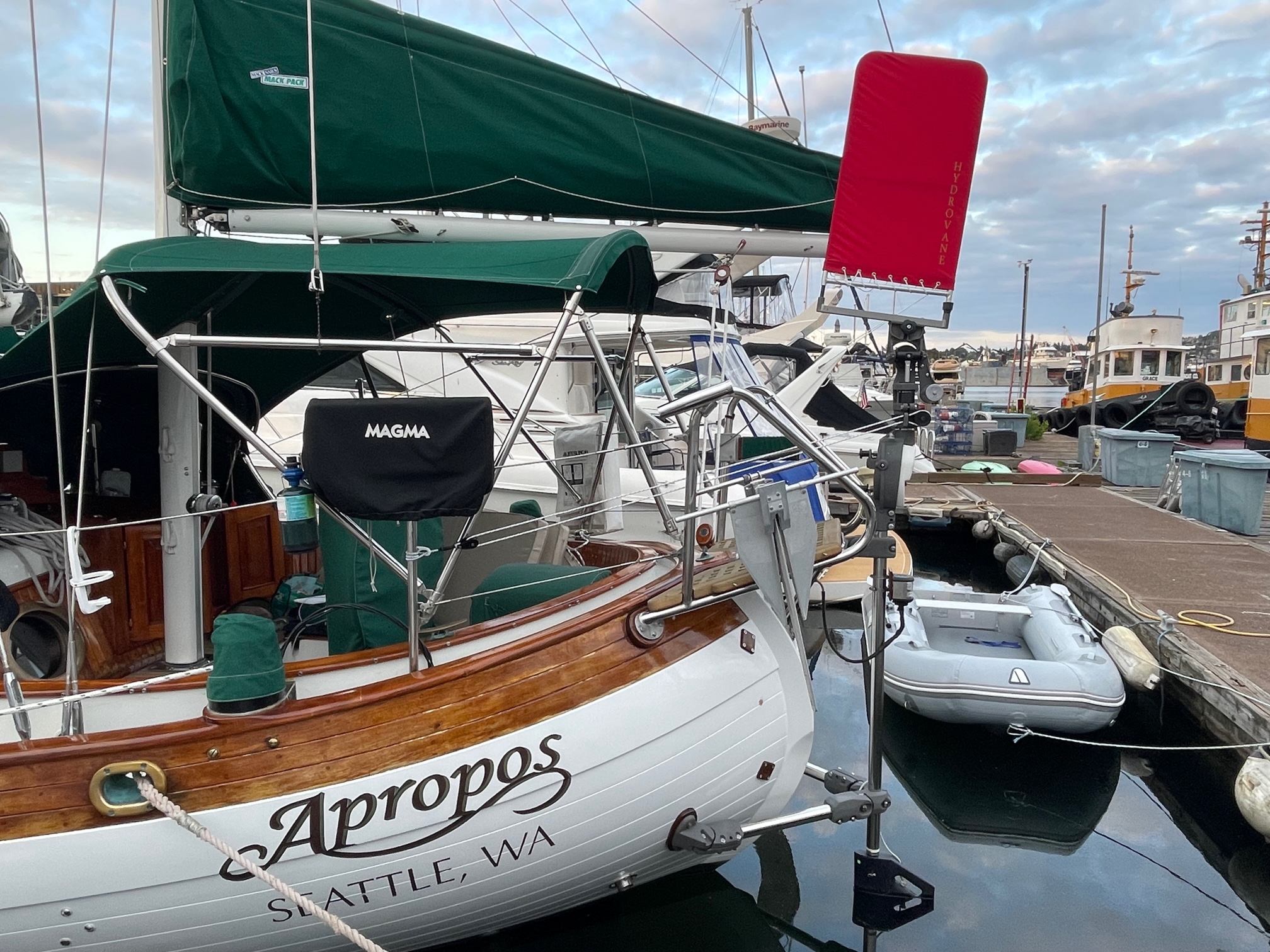
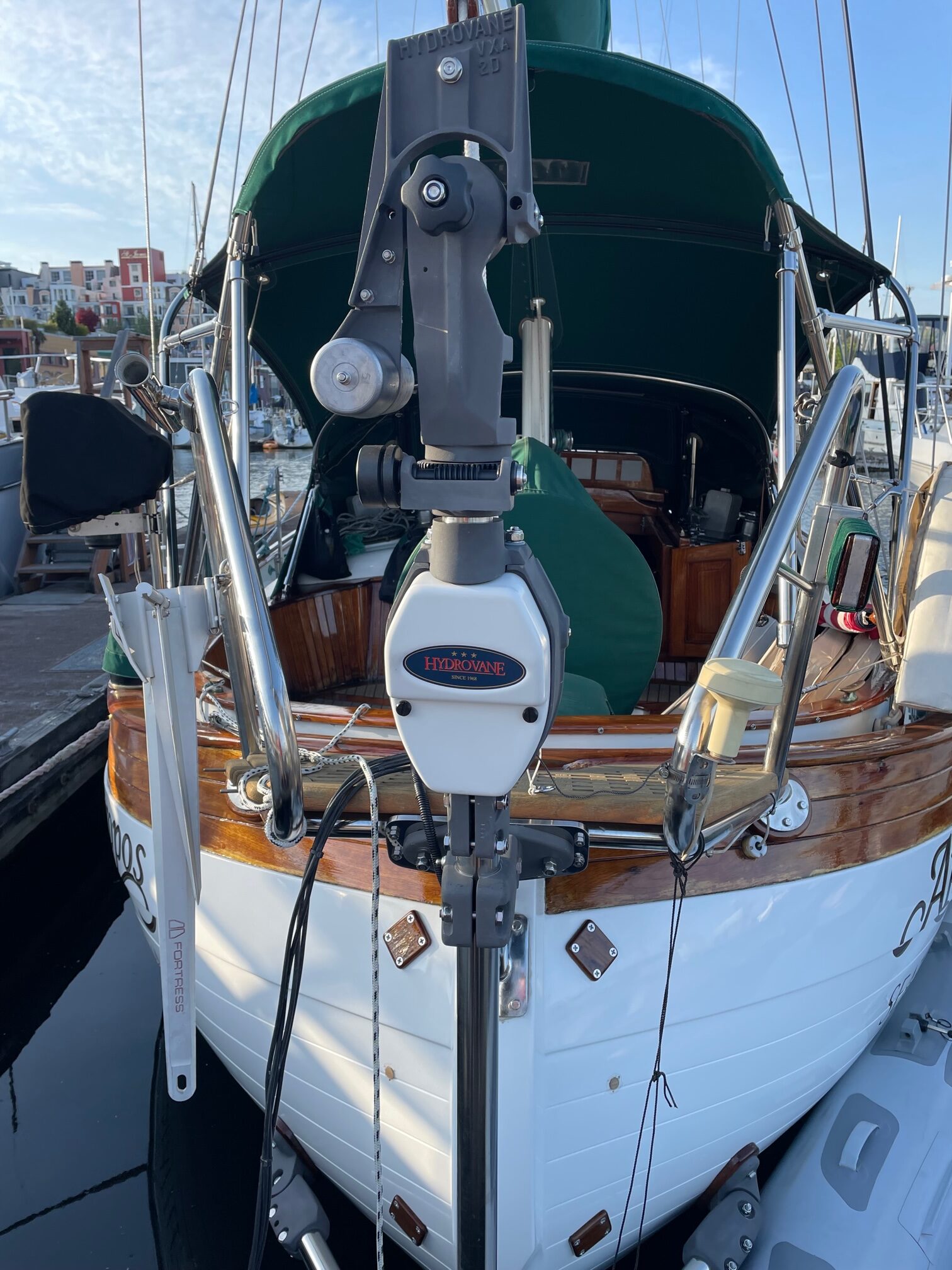
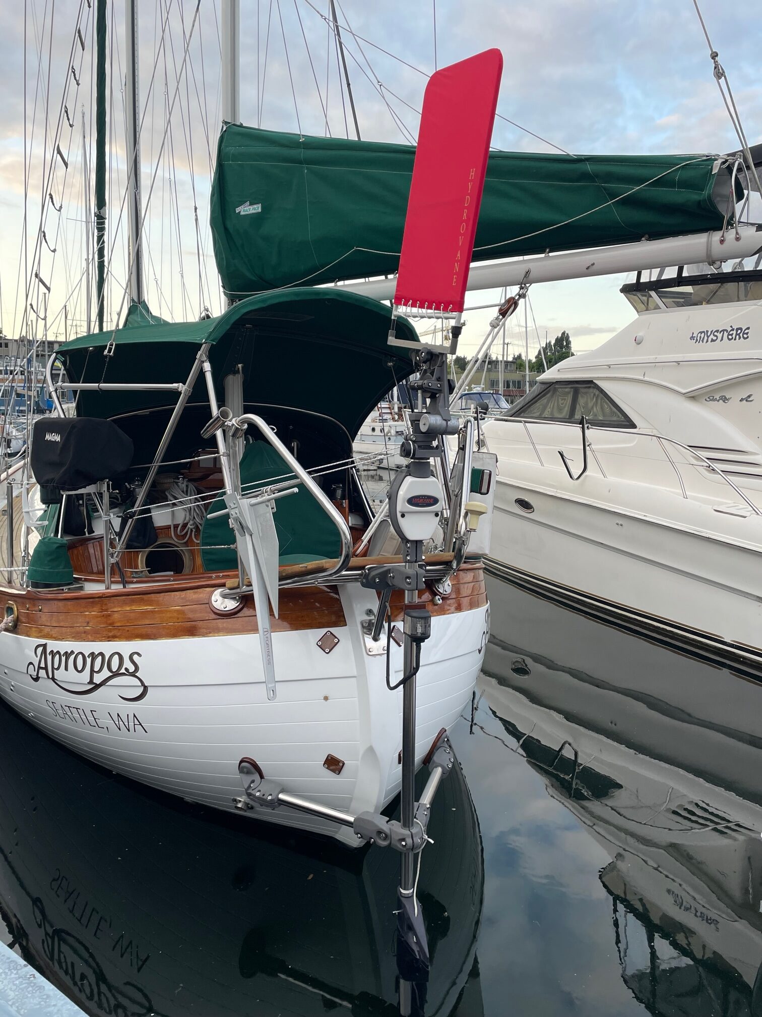
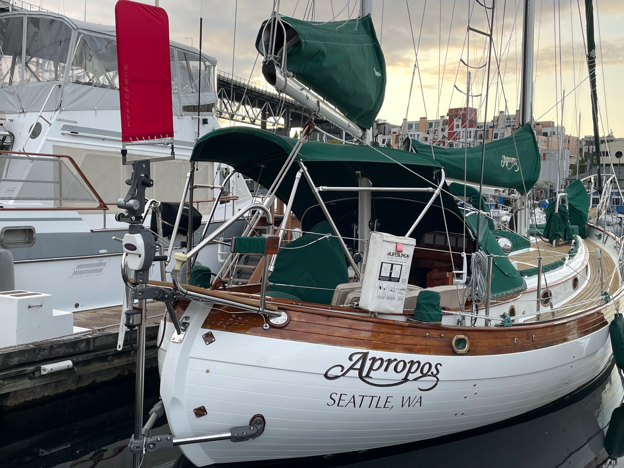
New Hydrovane Windvane
A Hydrovane self-steering windvane is an auxiliary rudder type system that drives its own rudder via a sophisticated drive unit linkage. Both the vane and the rudder are larger than the vane and paddle used in a servo-pendulum system. There’s an adjustment called a ratio knob that can be set according to wind conditions. The vane can also be adjusted up & down as well as pivoting to fine tune the sensitivity. The vane rotates 360 degrees via a continuous control line that extends into the cockpit, making it easy to adjust while at the helm.
Installation
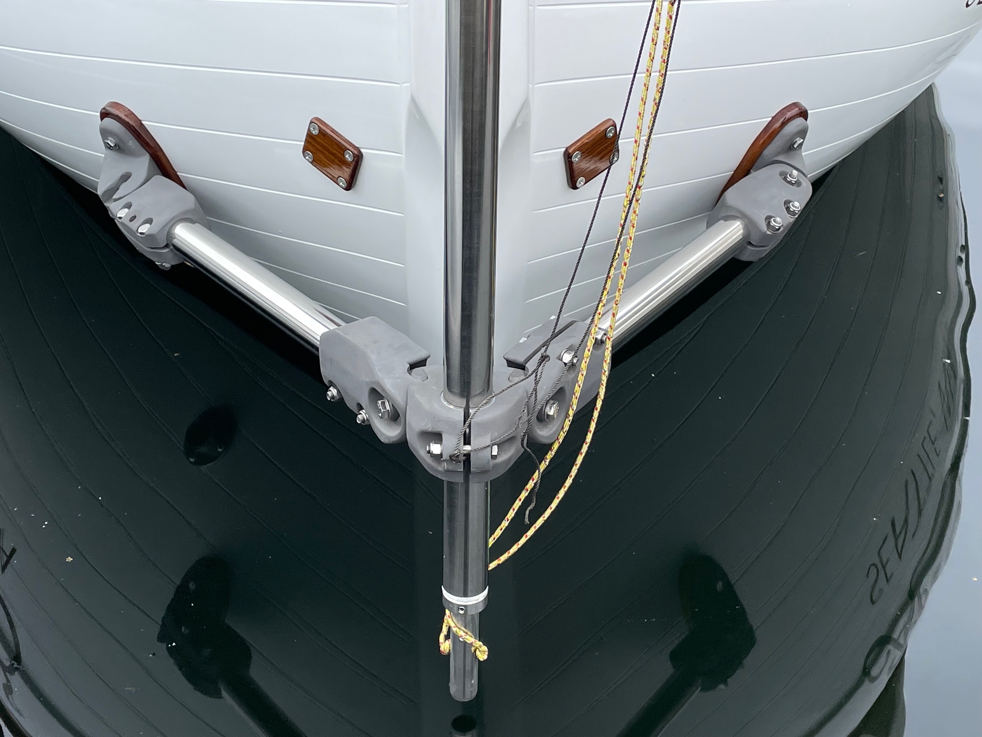
Although the Hydrovane can be mounted off-center, I decided to mount it on the centerline of the boat. Hydrovane provides the correct brackets and shaft needed for any boat, and for Apropos I needed an upper H bracket, a lower A bracket, and a longer shaft, and 2 mounting brackets, teak pads and backing plates. For every step of the installation, I tied safety lines to the parts in case something fell. I was able to work from the dock when installing the upper H bracket, and from a dinghy for the lower A bracket. The install instructions (booklet and video) provided by Hydrovane were very well done and easy to follow. Phone support from Richard and Will at Hydrovane was also very helpful with any questions I had.
For the upper H bracket, I had a custom stainless steel plate fabricated and mounted it to the stern platform with 3 U-bolts. The H bracket then got bolted to the plate for a very solid upper connection. Next I mounted the shaft to the H bracket. For the lower connection, an A bracket was used with SS tubes extending to mounting plates that through-bolted to the hull. I used 3″ pvc pipe in place of the SS pipe for determining the exact placement of the hull through-bolts. One of the most time-consuming parts was sanding the 2 teak pads that fit between the hull and mounting plates to the contour of the hull shape. For this, I taped 80 grit sandpaper onto the hull and moved the teak pad back and forth until there were no gaps (took over 2 hours per pad). I used aluminum backing plates inside the hull, and fastened them using thickened epoxy to increase the contact area of the plates. After the upper H bracket, shaft, and lower A bracket were all mounted, the drive unit was added to the top part of the shaft, and finally the rudder, vane and vane adjustment line. Here are some pictures taken during the installation.
U-Bolts for SS PlateH Bracket Mounted to SS PlateA-Bracket (pvc pipe to determine exact position of hull mounts)Shaft Vertical PositioningAfter Sanding Teak to Hull ShapeInside Hull Mounting PlateEpoxy on Mounting PlateTeak Spacer and Brackets Mounted to HullDrive Unit Mounted on ShaftVane Added
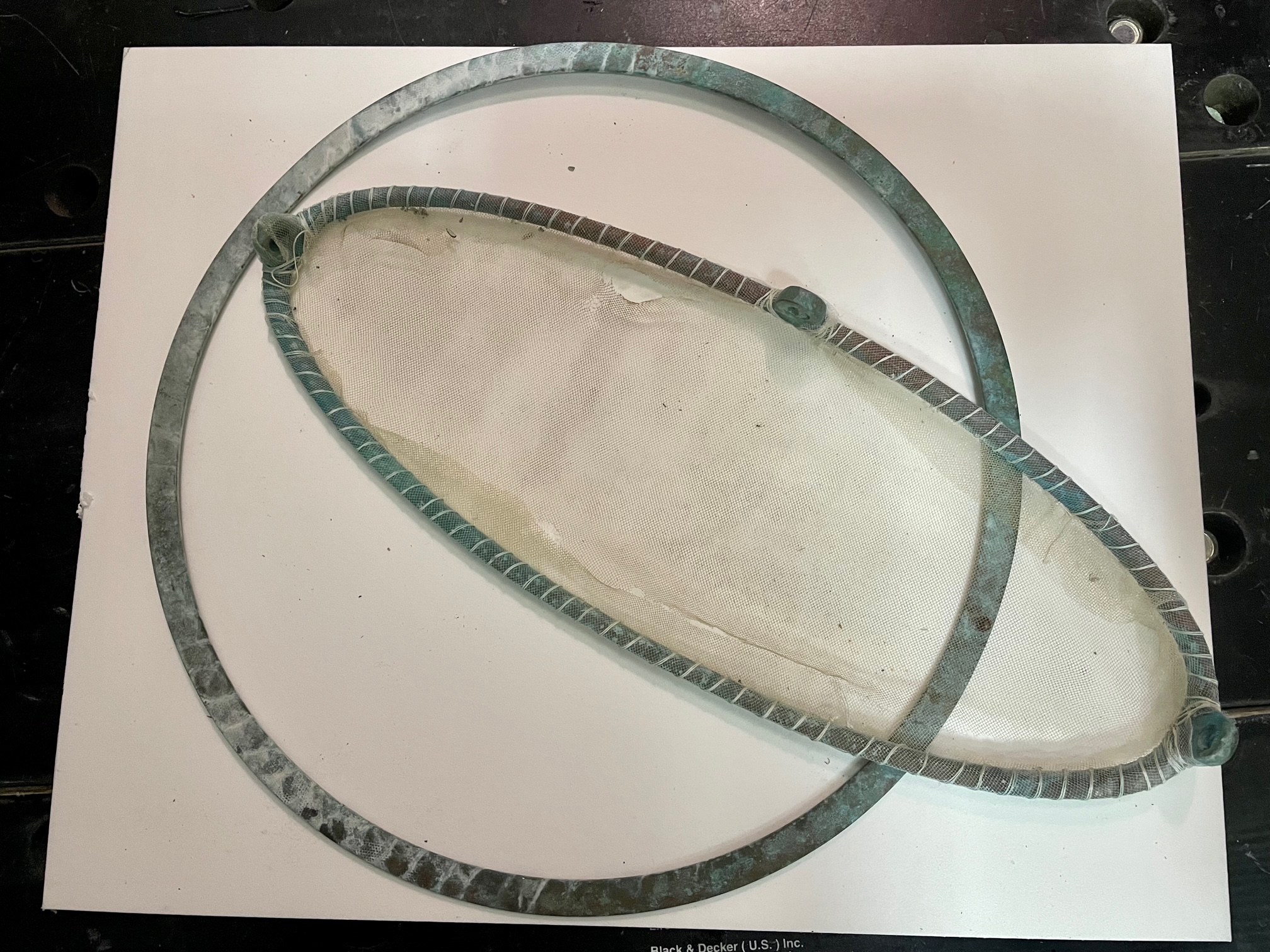
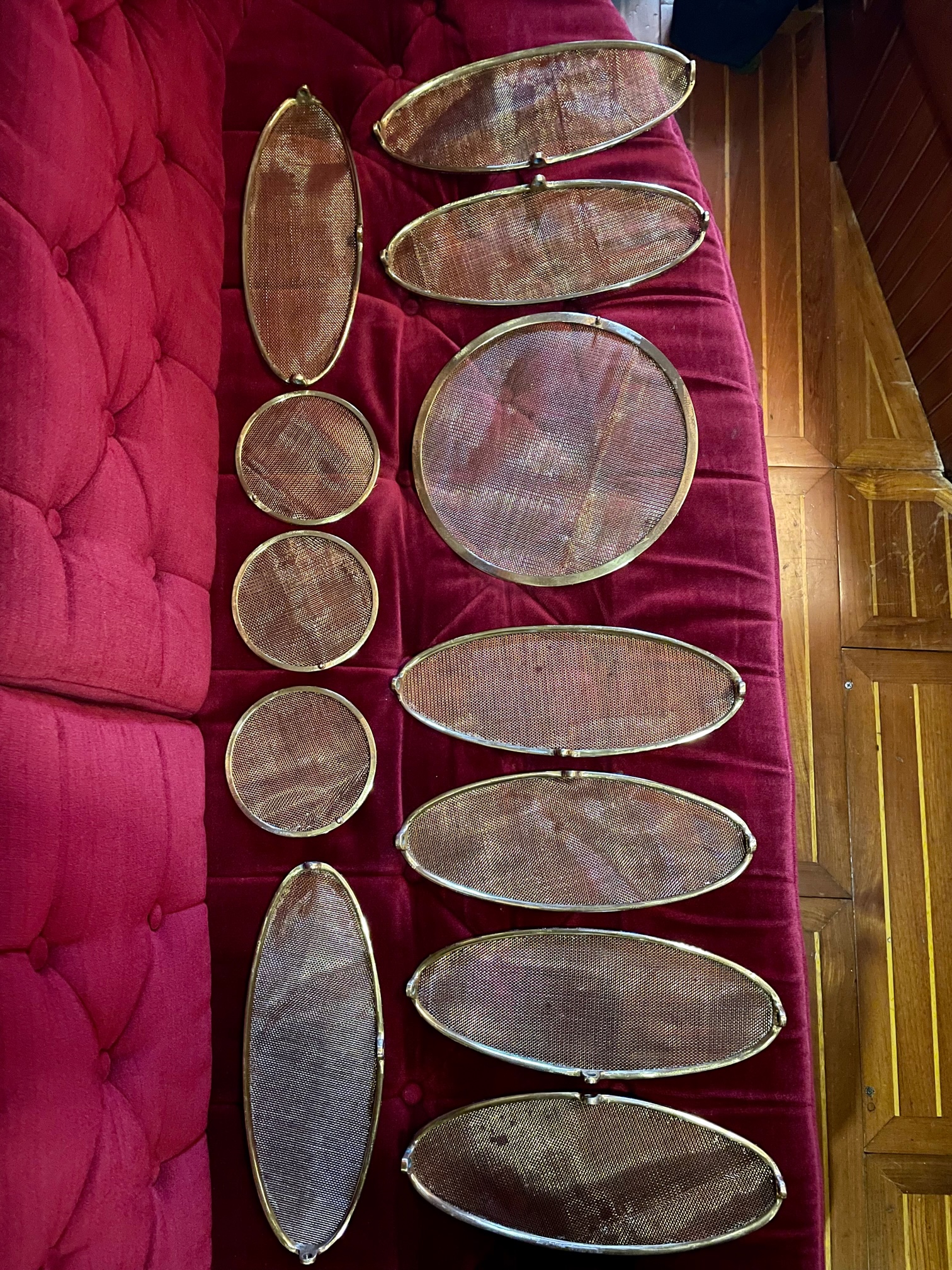
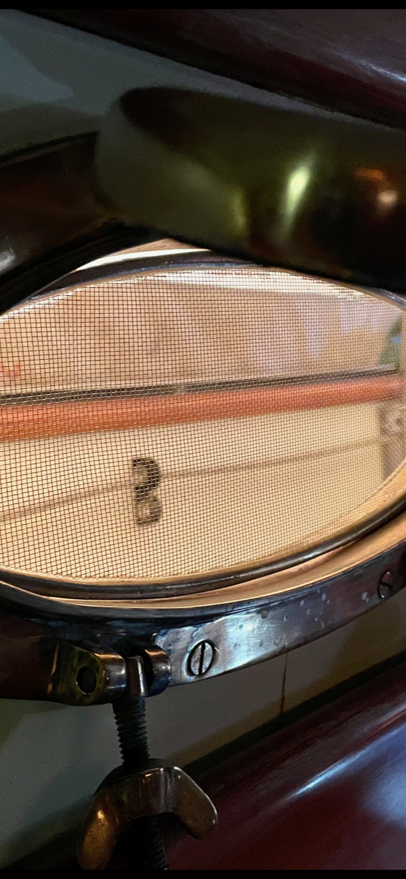
Apropos came with 8 oval, 3 small round, and 1 large round bronze port screen rings. After arriving in Mexico, we realized we needed them to keep out bugs, mosquitos, and no-see-ums (tiny flies that bite) since we had to keep the ports open for ventilation. The problem was that the frames had no screens, so we hastily added some fine mesh fabric by wrapping polyester thread (same as used for sails) around the edges of the rings. This worked well for the year it was needed, but eventually the mesh fabric became brittle and easily torn.
Frames with old fabric mesh
After removing the fabric and thread, I soaked the frames in a metal cleaner, then used a dremel tool to polish them. Next I coated them with Protecta-Clear. I had about a yard of bronze screen that came with the boat, so I cut pieces slightly bigger than each frame. I ran a bead of Gorilla glue on the frame, placed the screen on wax paper and the frame on top the screen, then a 5 gallon bucket of water to apply pressure for 2 hours while the glue cured. The final step was to trim the screen along the edges with a pair of scissors. Here are all 12 finished rings and a picture of one of the oval port rings in place.
Finished adding screens to port ringsOval screen in port opening
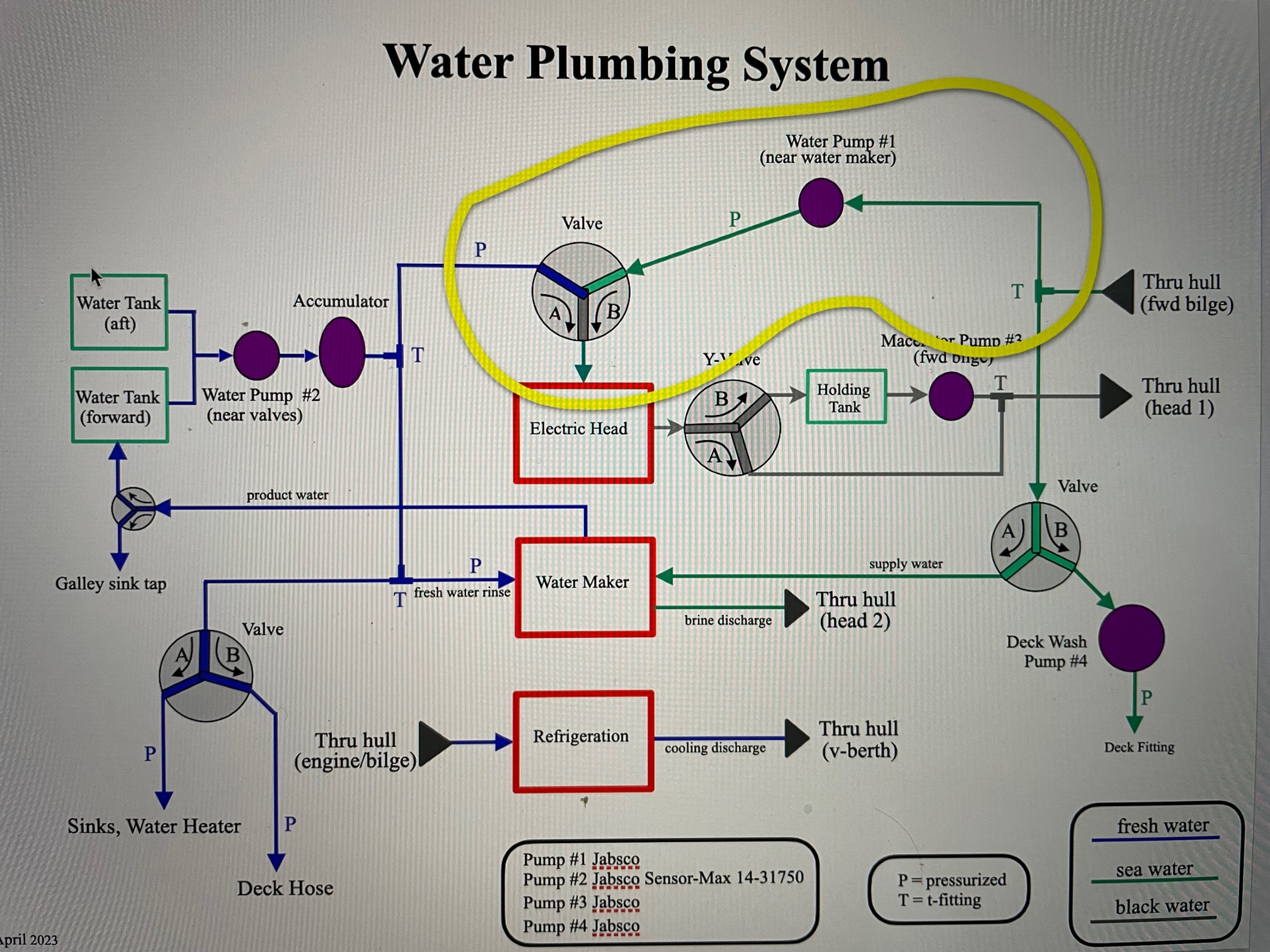
About a year ago I replaced the old manual head with a new electric head. I plumbed it with fresh water fill/flush but wanted to add a sea water option. The fresh water option will be used whenever there is easy access and abundant water. When sailing offshore or cruising in areas where fresh water isn’t easily available, the head would be switched over to using sea water.
I added a 1:2 valve, a Jabsco pump (taken from the old refrigeration system), and T’d into the sea water input for an easy project that was accomplished in a weekend. Here is a drawing of the project showing the new plumbing inside the yellow boundary. The green lines represent sea water and the blue lines fresh water. The sea water pump is wired to the electric head control board so when the fill button is pressed, the pump will activate. A disconnect switch was added to open the wiring to the sea water pump when the system is in fresh water mode.
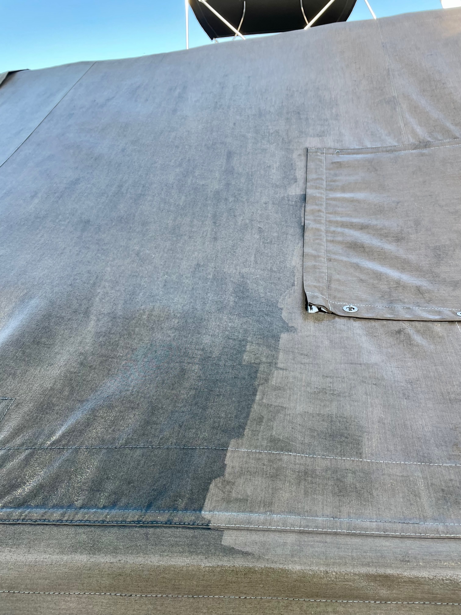
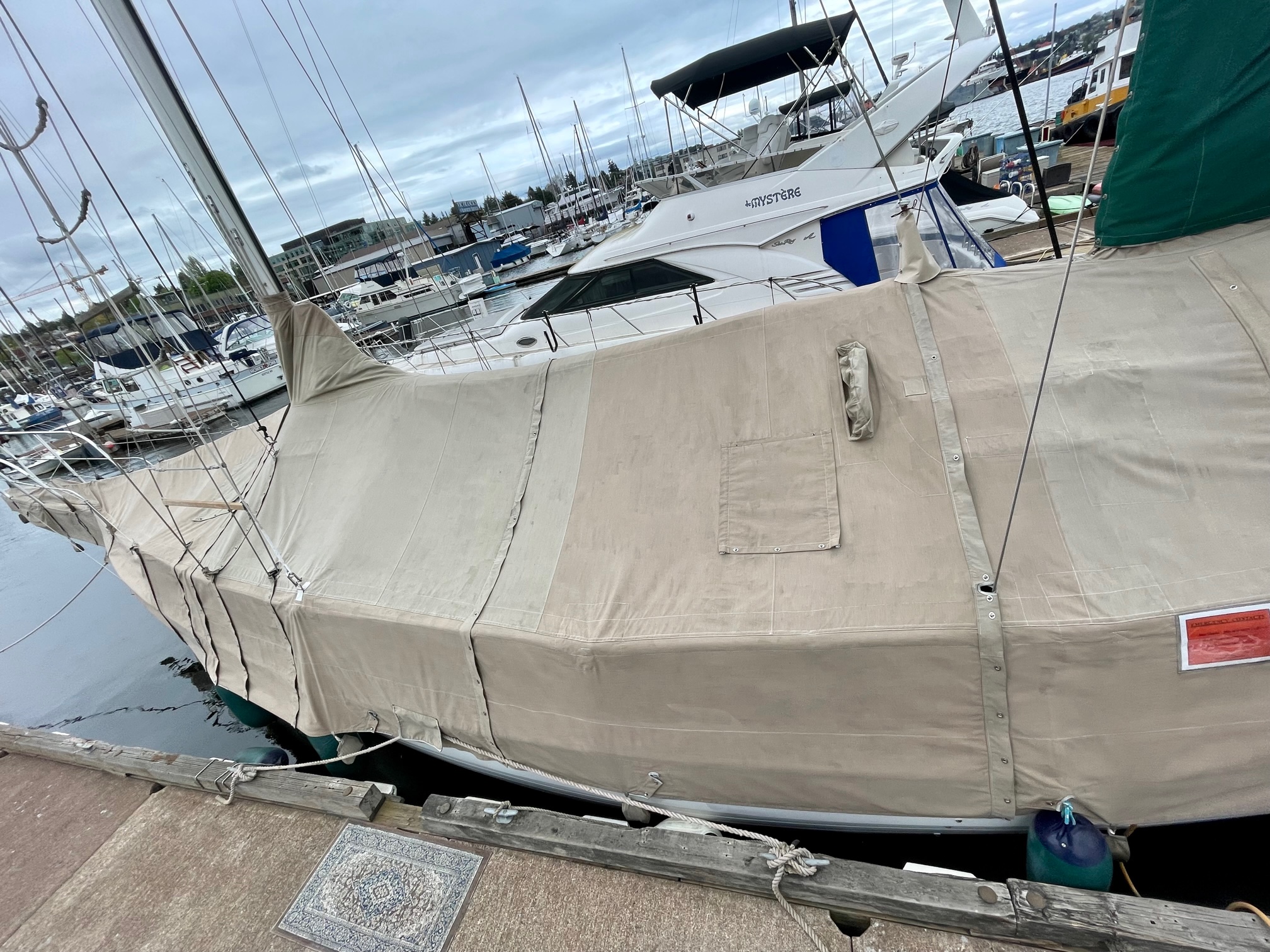
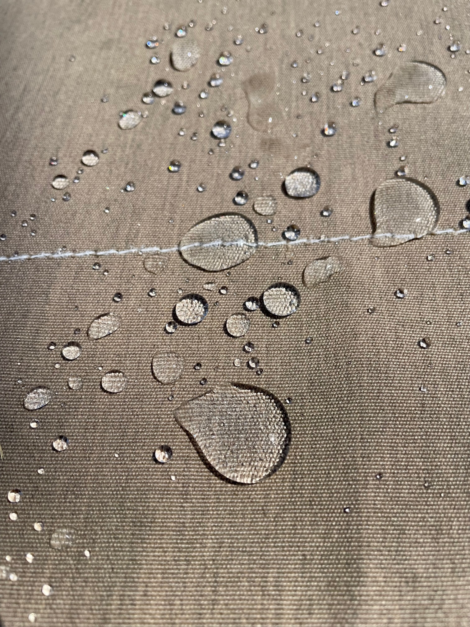
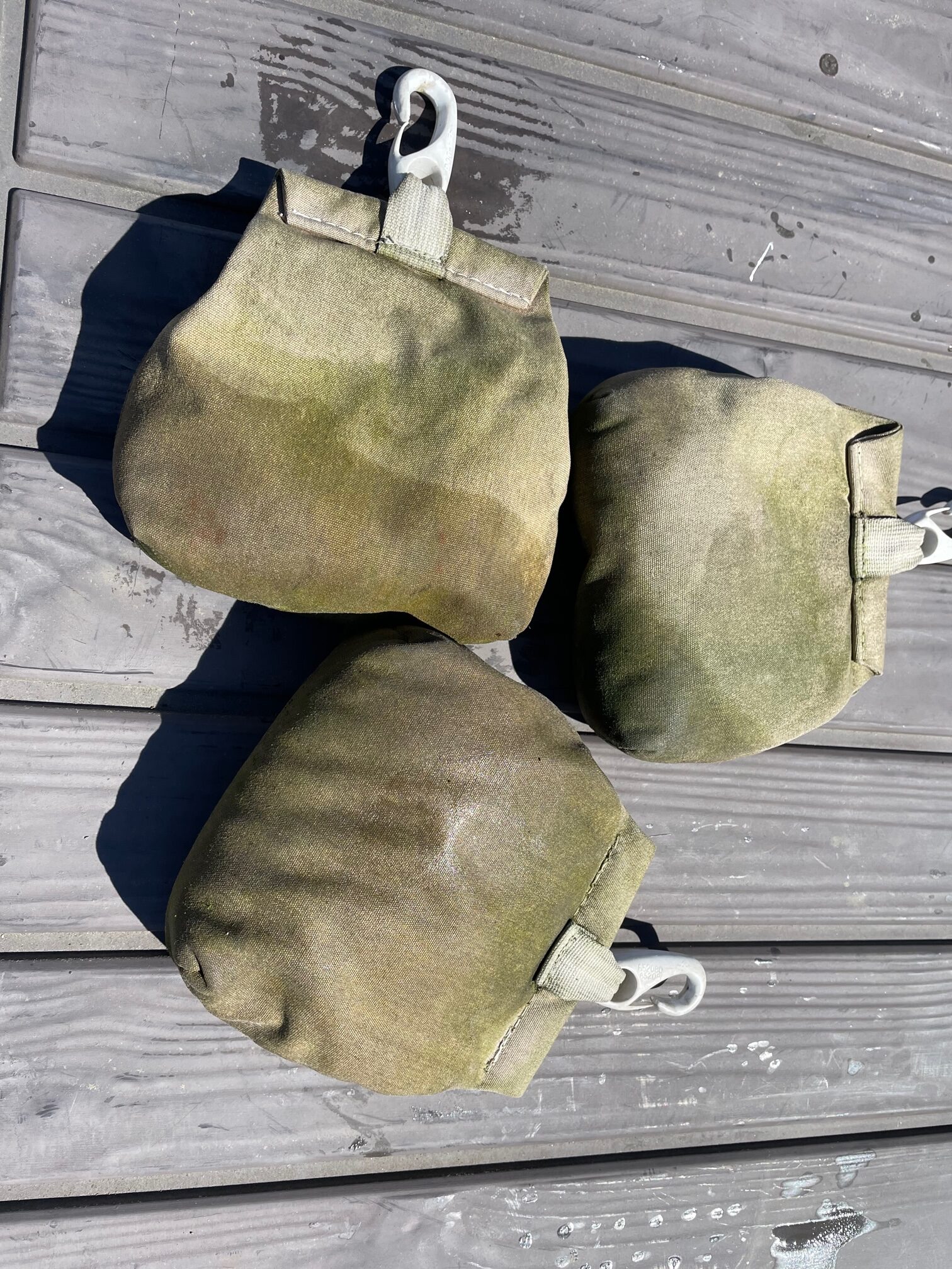
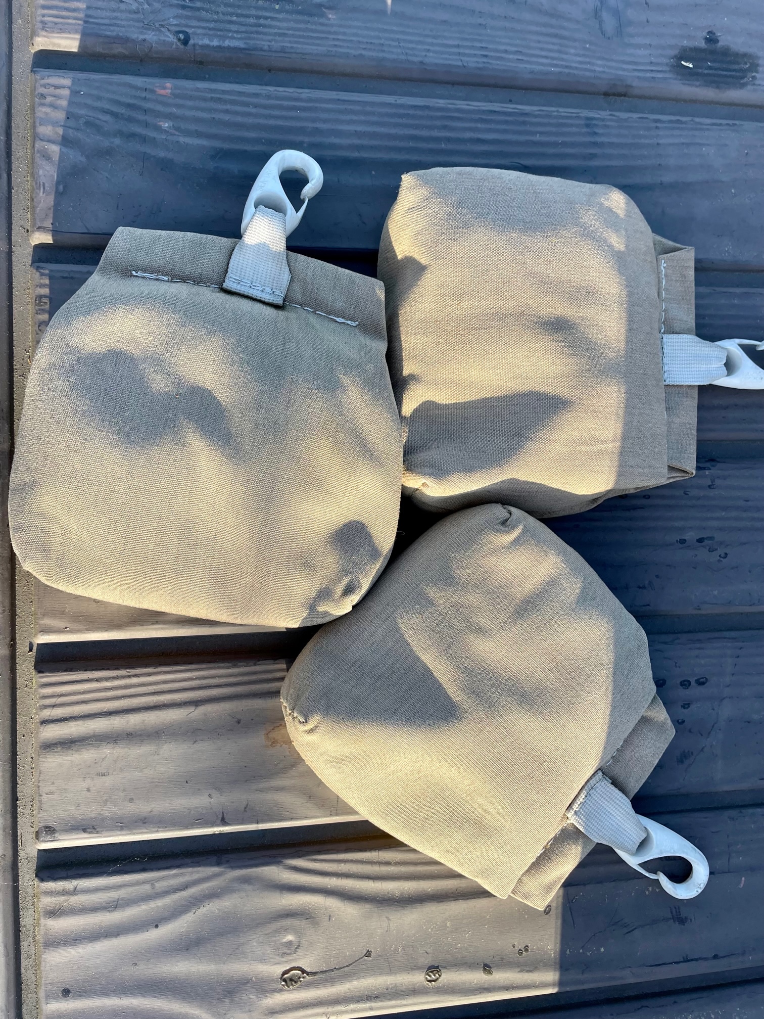
The boat cover has been used for 15 years worth of Seattle rainy winters. It goes on around November 1 and comes off by mid to late April. The cover was custom made using marine canvas (Sunbrella) with zippers and twist locks connecting 4 large sections. I usually rinse it with a hose, allow it to dry, and pack it inside 2 huge duffel bags, then store it in a garage until bringing it back out for the winter. Over the years it has accumulated quite a bit of dirt and mildew, so this year I decided to clean it well. I started with a hose and a canvas cleaning product, lightly scrubbing it with a soft brush and then rinsing. This did very little in the way of making it look any cleaner. So I decided to bring out pressure washer and that made a huge difference. It took a few hours of spraying at close range to remove most of the grime, but it came out looking almost new. After drying well, I applied 3 gallons of 303 Marine/Aerospace protectant using a garden sprayer. This gives it UV protection, and makes it water repellent and stain resistant. I also cleaned and treated the 18 canvas bags that hold sand used as weights that clip on along the bottom of the cover.
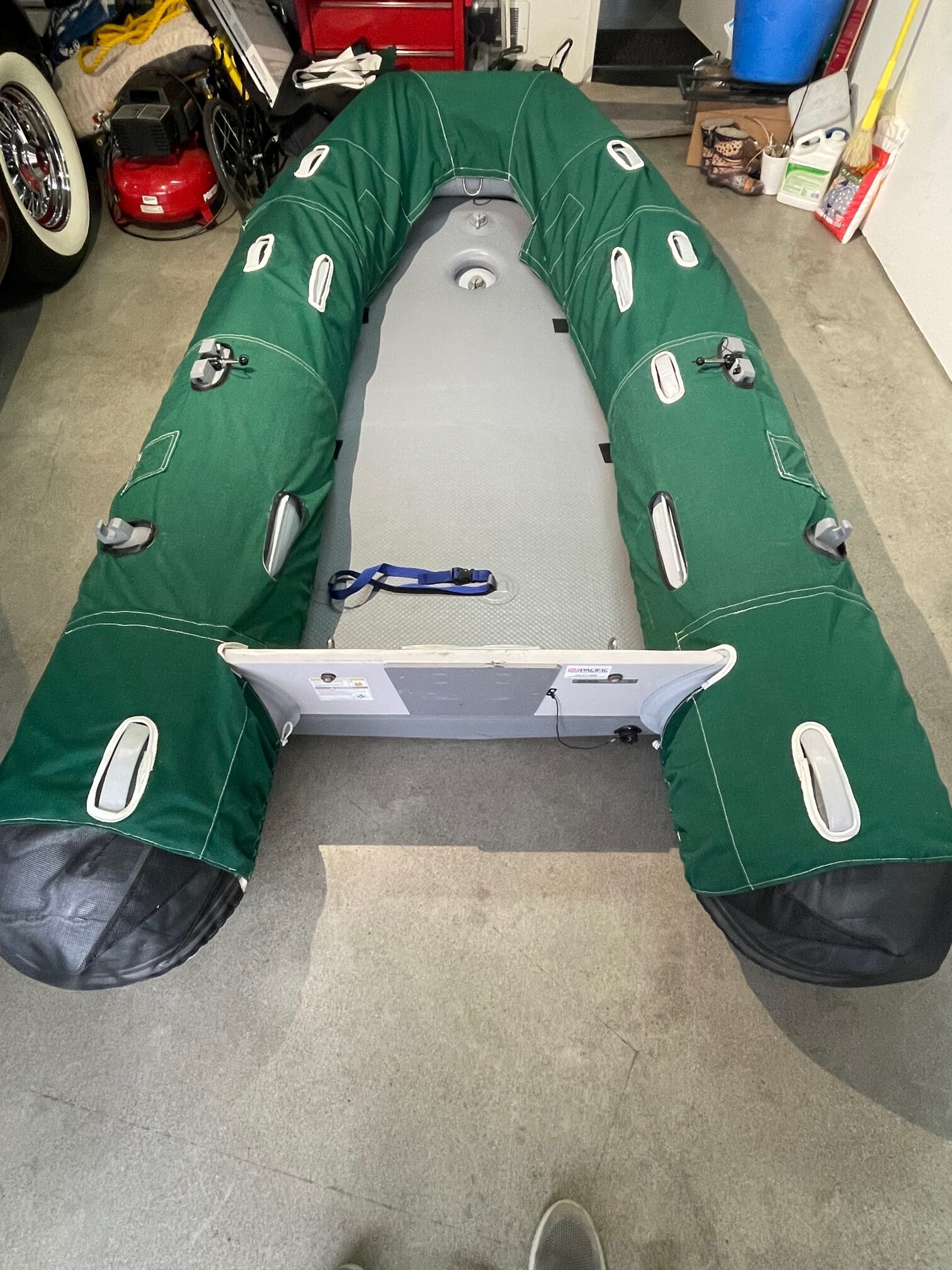
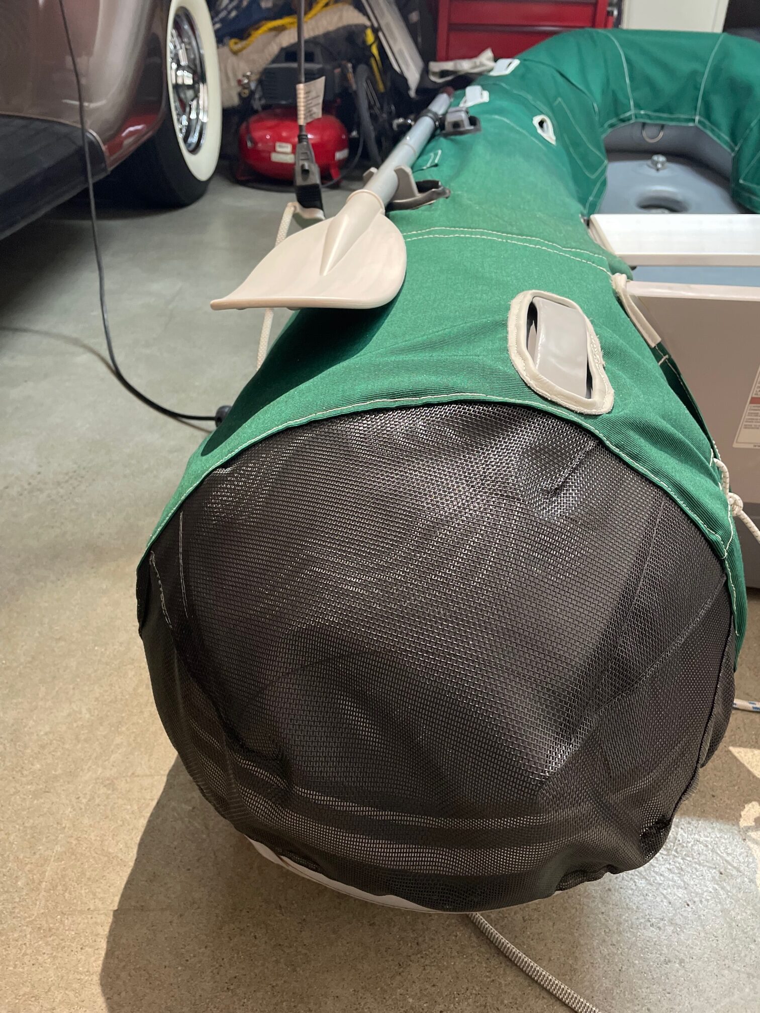
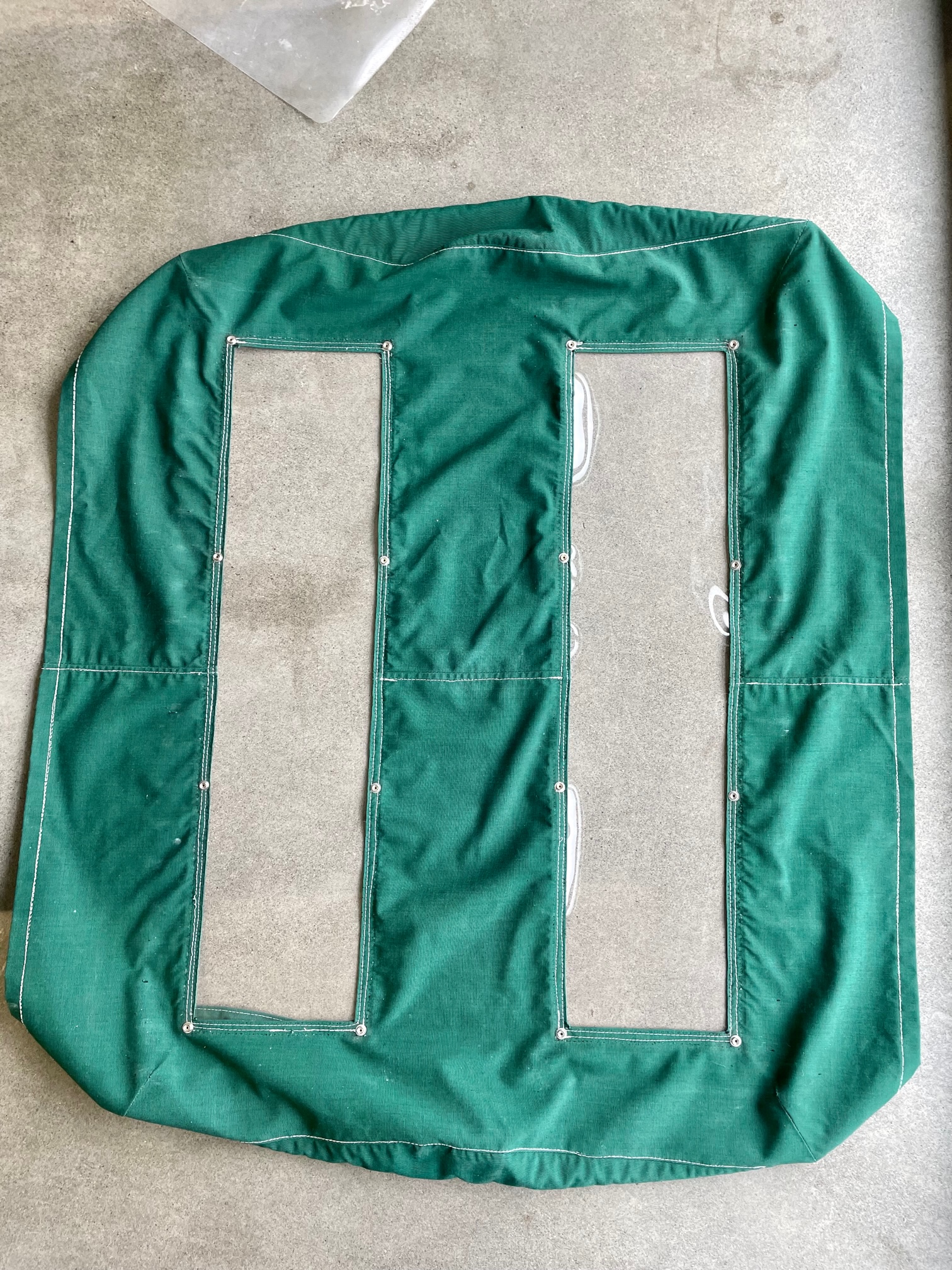
We had canvas dinghy chaps made when we were in Mexico to help protect the dinghy from UV exposure. It was custom made for the dinghy, so 9 years later when we got a new dinghy, it no longer fit. I tried modifying the chaps, but wound up replacing most of the Sunbrella canvas to get a better fit. It’s my biggest sewing project using a Sailrite machine and I got pretty good with it. I also re-stitched some of the other canvas covers for the boat, and replaced the vinyl in the butterfly hatch cover and the forward hatch cover since both were over 10 years old.
Handle Cutouts Lined With LeatherMesh Phifertex Butterfly Hatch Cover New Vinyl
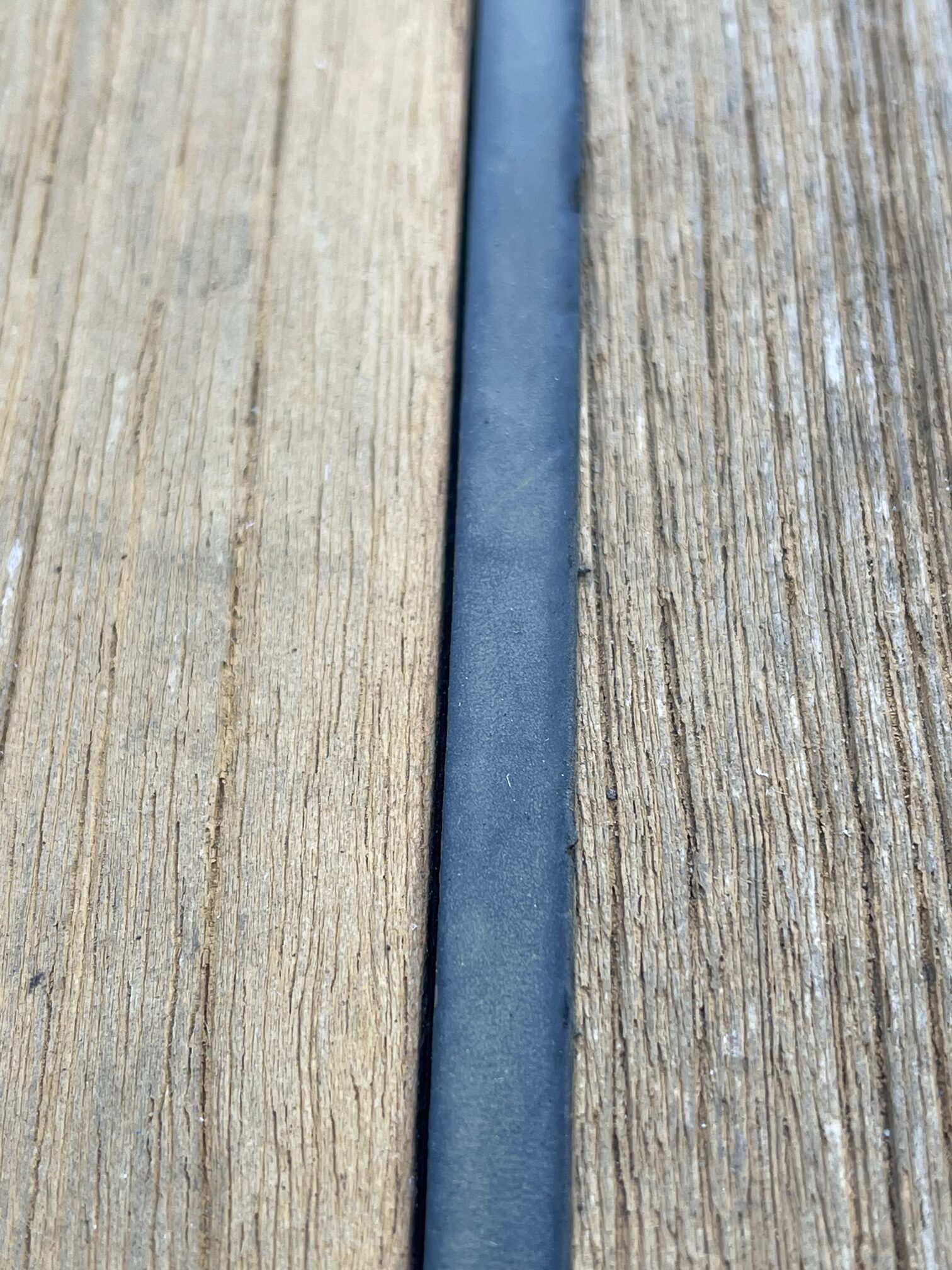
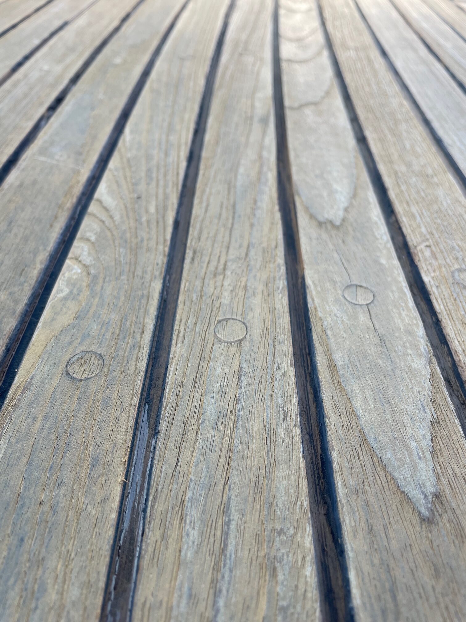
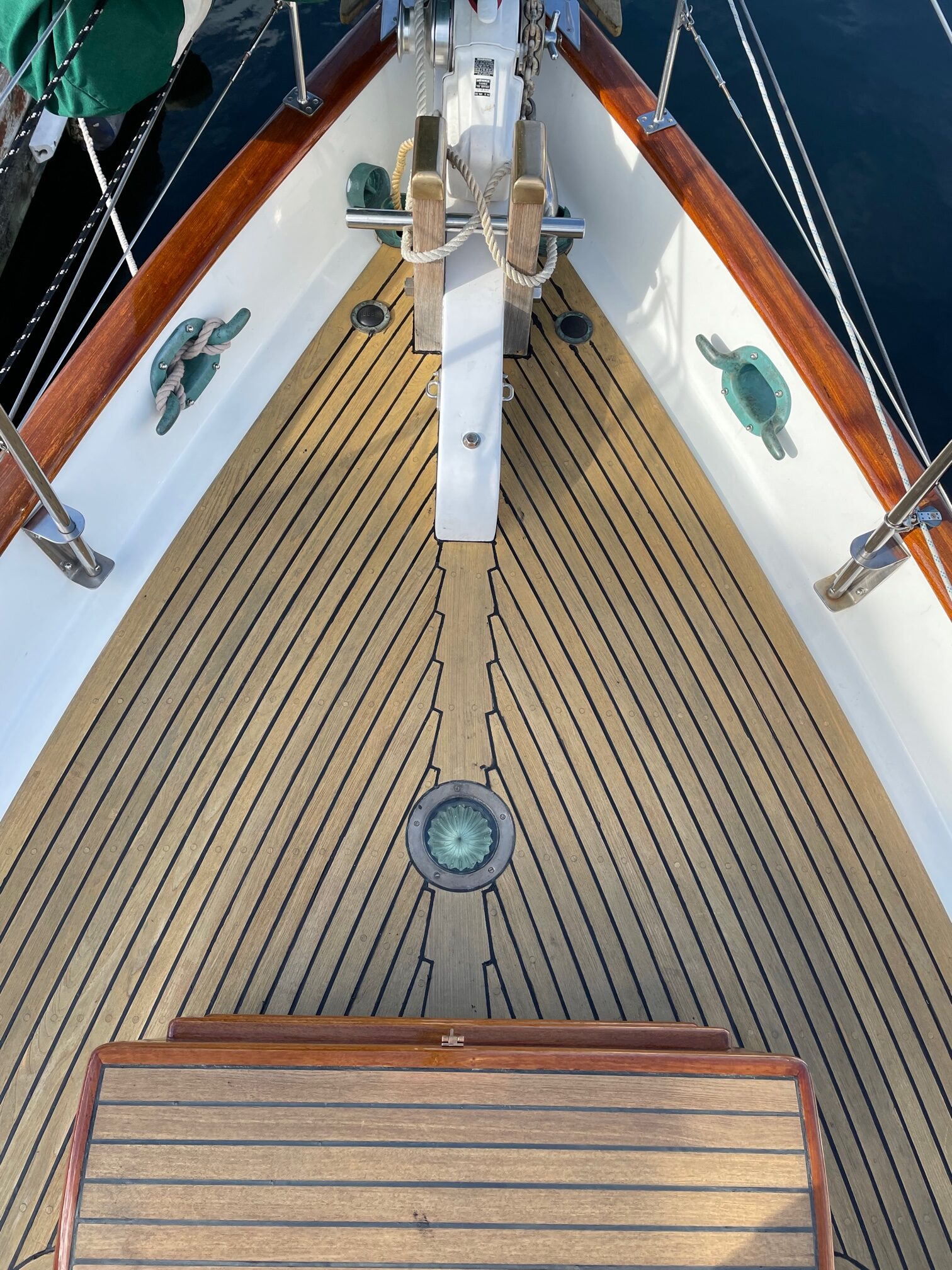
The teak decks on Apropos are 40 years old and still in pretty good shape. Much of the caulking is also in decent shape but there are places where it has separated from the teak. This allows water to sit between the teak and caulking. These areas can be seen when a wet deck is drying since they are the last to dry.
Gap between caulking and teak
The fore-deck teak had a lot of these caulking gaps so I decided to start there. Using a utility knife to score both sides of the caulk, and a Teakdecking Systems Reefing Hook, I removed all the old caulking. Next I sanded the U-shaped channels, vacuumed, and cleaned with Acetone.
Caulking removed and channels cleaned
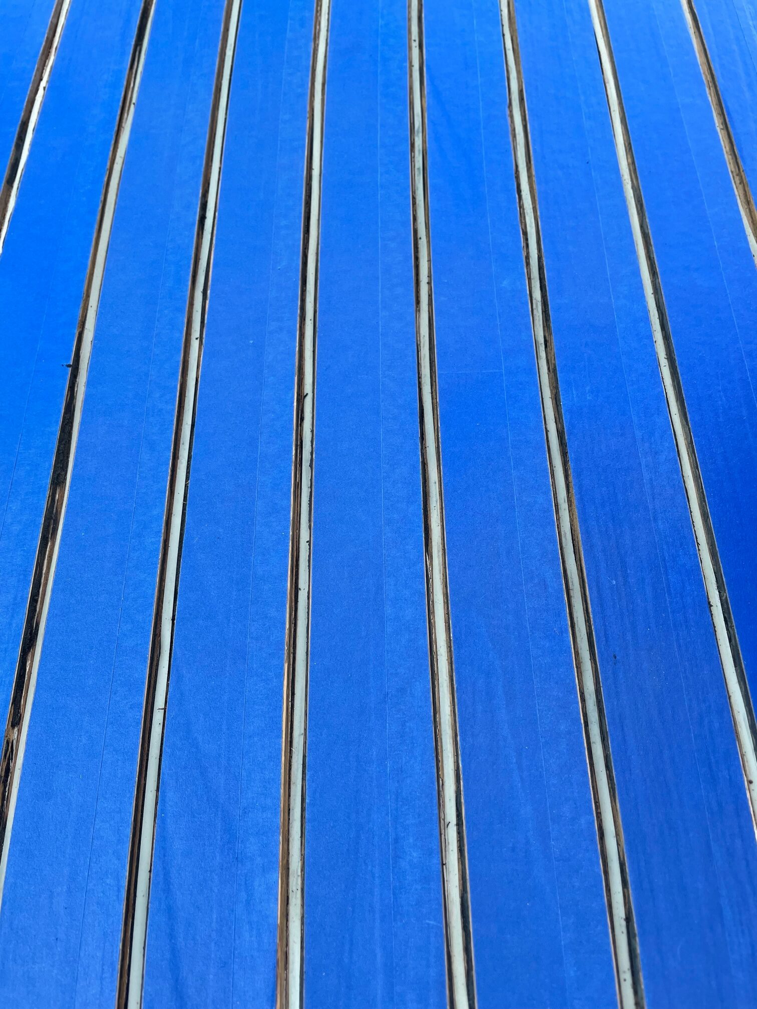
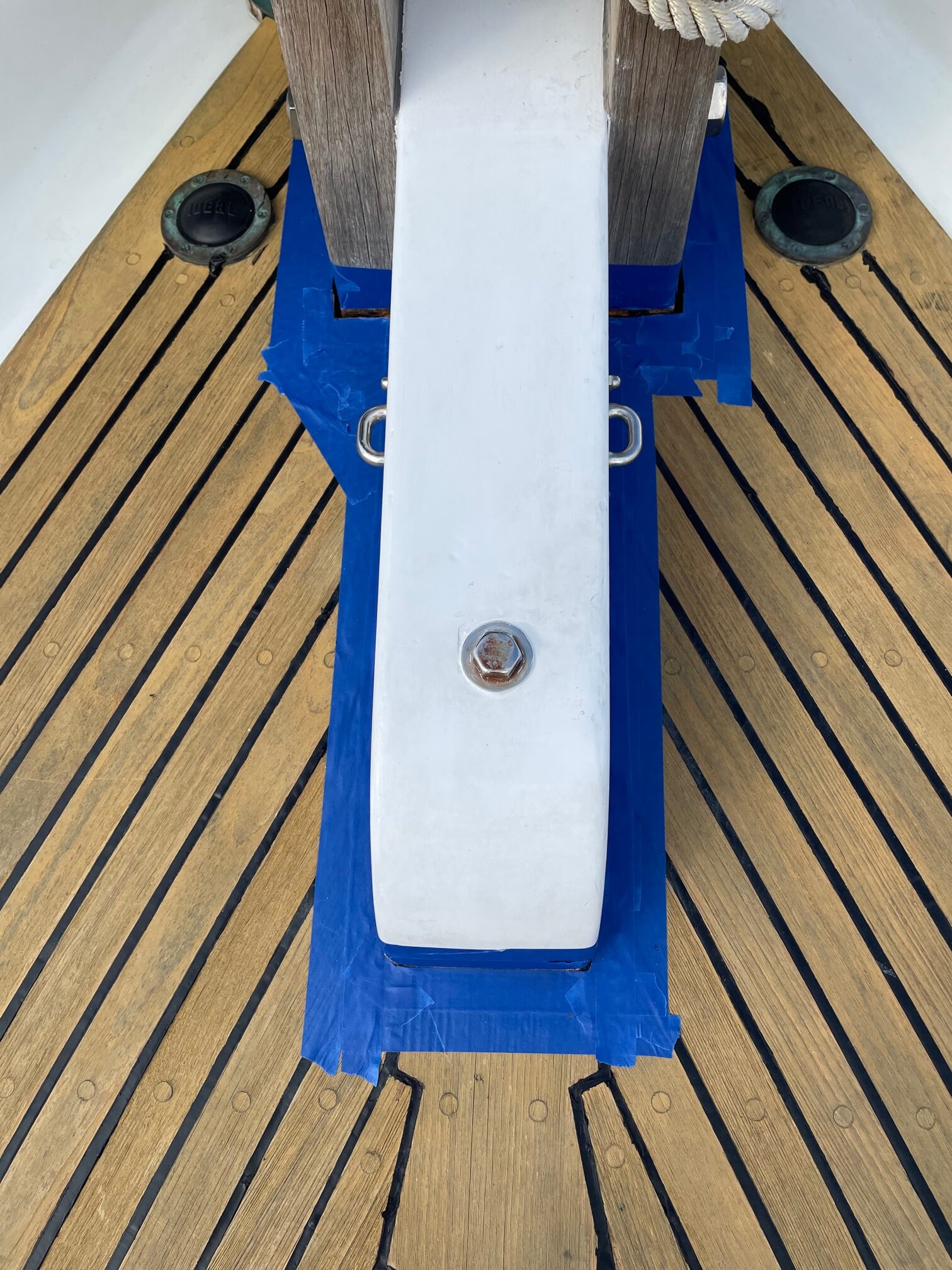
Next was the tedious job of taping the teak. I used Scotch brand blue painters tape. This method requires much less sanding which is important with 40 year old decks. I used 3/16″ fine-line tape to line the bottom of the channels, as recommended by Teakdecking Systems. This prevents the caulking from bonding to the bottom of the channel and allows it to expand and contract with the constant movement of the boat deck.
Taped Decking
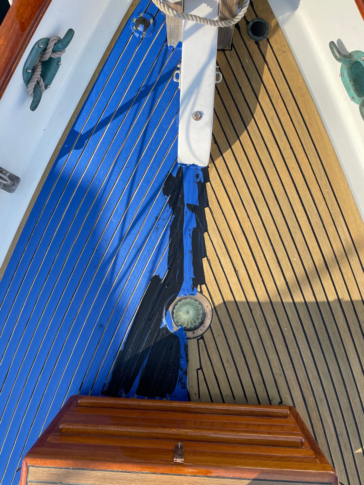
Finally, I applied the Teakdecking Systems SIS 440 caulk. The method I used was to over-fill the channel, then use a metal putty knife to apply pressure to remove any air gaps and remove excess caulk. After sitting for 5 minutes, I peeled off the blue tape. The entire fore-deck took 6-10oz tubes of caulk.
Half Way Done
After the caulk cured for 5 days, I sanded with 80-grit paper to smooth out the caulk and make it flush with the teak. Here’s the final result.
Re-Caulked Teak Decking
About half a tube of caulk was used to fill the deep gaps between the decking and aft bowsprit and chocks shown here. It’s important to keep water from leaking around the bowsprit and chocks.
The refrigeration on Apropos has been inoperable for a long time. During our South Pacific trip, we shut the freezer down after departing Mexico for French Polynesia–it was consuming too much power for our solar to keep up with and we knew there would be no docks to plug into for the rest of the trip. We replaced it with a portable Dometic refrigeration box that found a place on the cabin floor in the v-berth. It eventually got moved closer to the batteries on the aft port-side cabin floor. It worked well but took up valuable floor space (24″ x 16″). After returning to Seattle, it was a low-priority project until now.
The Old System
The old system was very complex. It was a Glacier Bay 12VDC water-cooled, cold-plate system. It was installed in 2004 and was run continuously for about 10 years, but Glacier Bay went out of business so parts were no longer available. It had 3 zones–a refrigeration box, a freezer box, and an air conditioning zone (we never really used the air conditioning zone except to try it out a few times). There was a solenoid valve for each zone and only one zone could be active at a time. There were many feet of refrigerant carrying copper tubing that ran from the compressor to each of the 3 zones. It had 2 remote display/control panels for setting and reading temperatures in the freezer and refrigerator boxes. We discovered soon after arriving in Mexico that the refrigeration system was running too often, most likely due to the lack of good insulation of the boxes. While in Mexico, I bought a sheet of 1″ foam closed-cell insulation from a hardware store and lined both boxes, but it was a sloppy job trying to fit the insulation around the cold plates. Soon after, we gave up on it and began using the Dometic portable refrigerator.
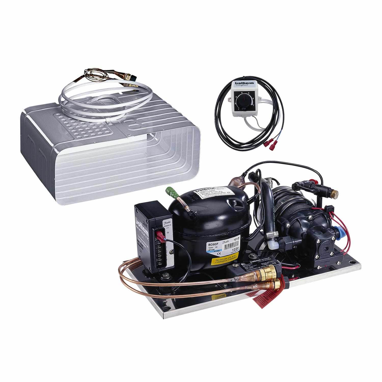
The New System
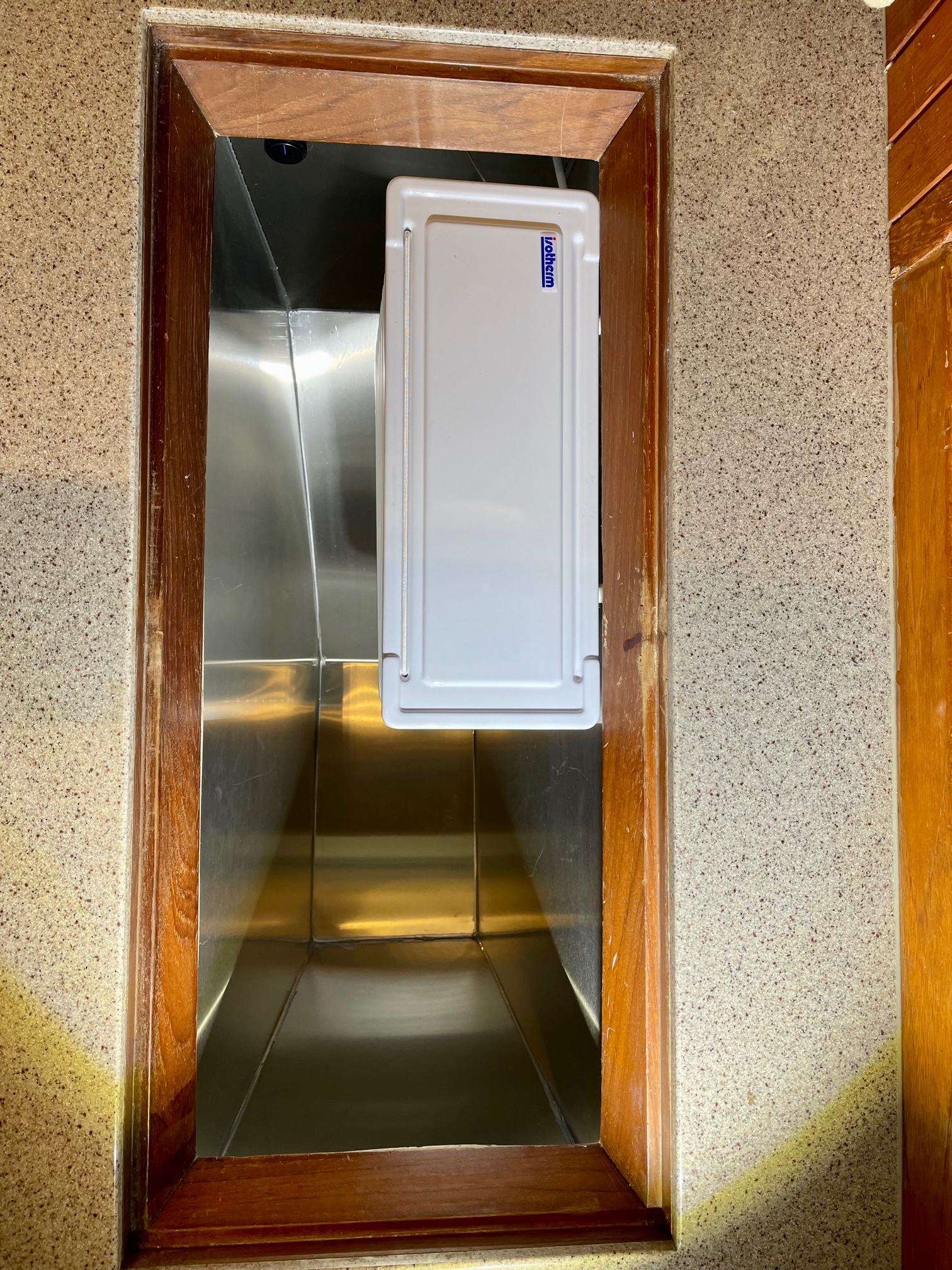
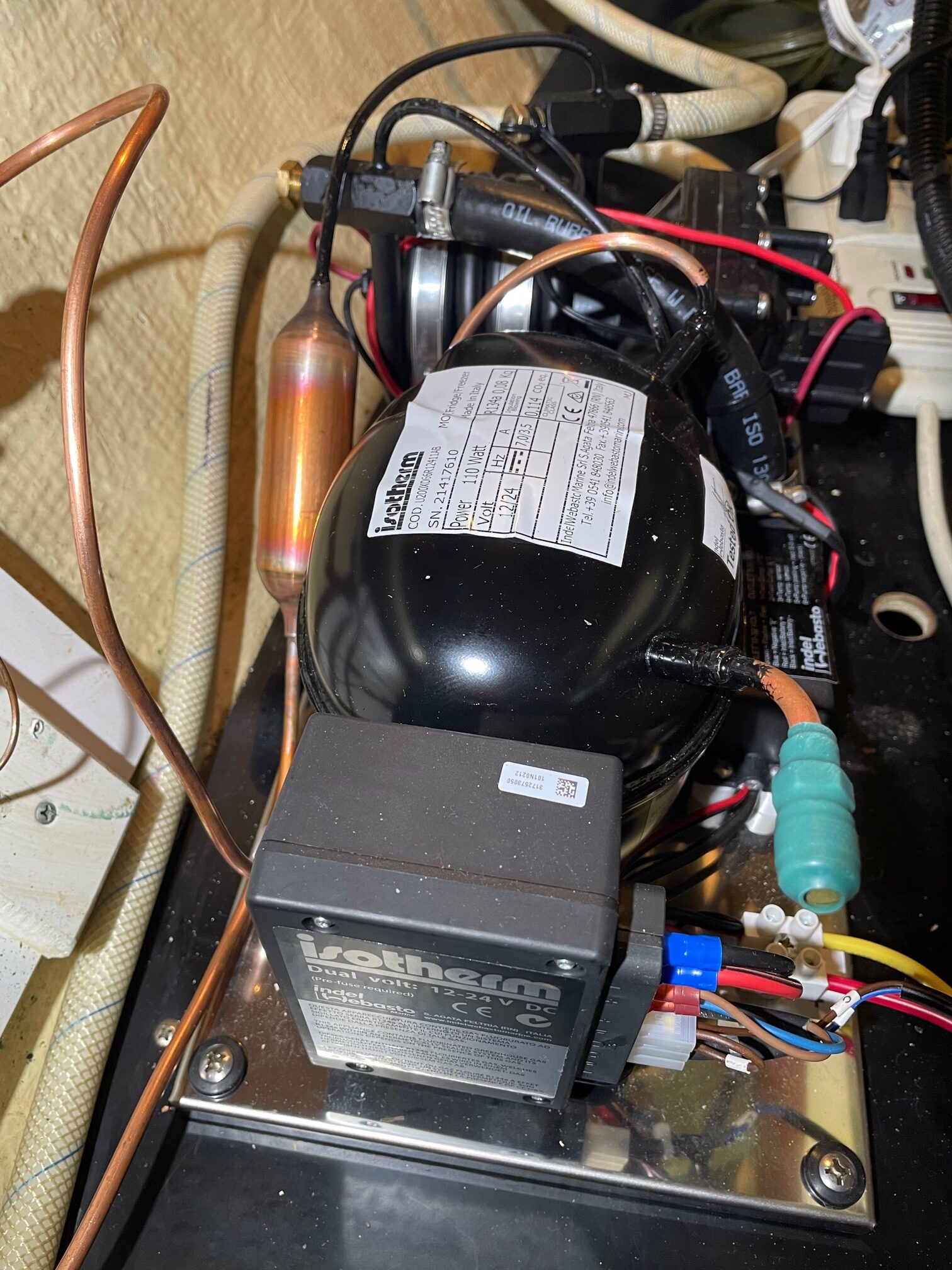
I chose an Isotherm Magnum 2505. It’s a 12VDC sea-water cooled system with an O-evaporator and built-in pump. I decided to keep it simpler by only having a refrigerator box, and convert the old freezer box to dry storage. The freezer box was very small and top-loading, and being tucked into a corner of the countertop, it was hard to access especially the lower half. For the amount of food it held, it wasn’t worth the energy it took to keep things frozen. The O-evaporator is like having a mini freezer within the refrigerator–with just enough volume to freeze a few items. The system comes fully charged with quick-connect self-sealing valves for easy installation–no refrigerant technicians needed. The compressor is industry standard Danfoss/SeCOP and is designed for volumes up to 7 cubic feet.
Isotherm Magnum 2505
Installation
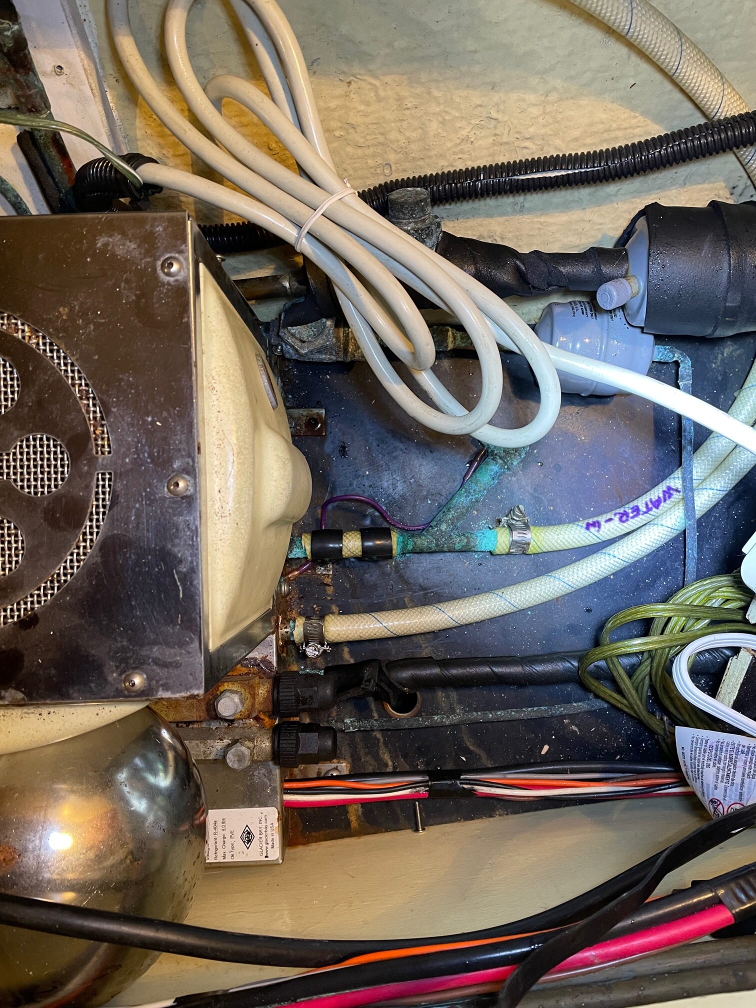
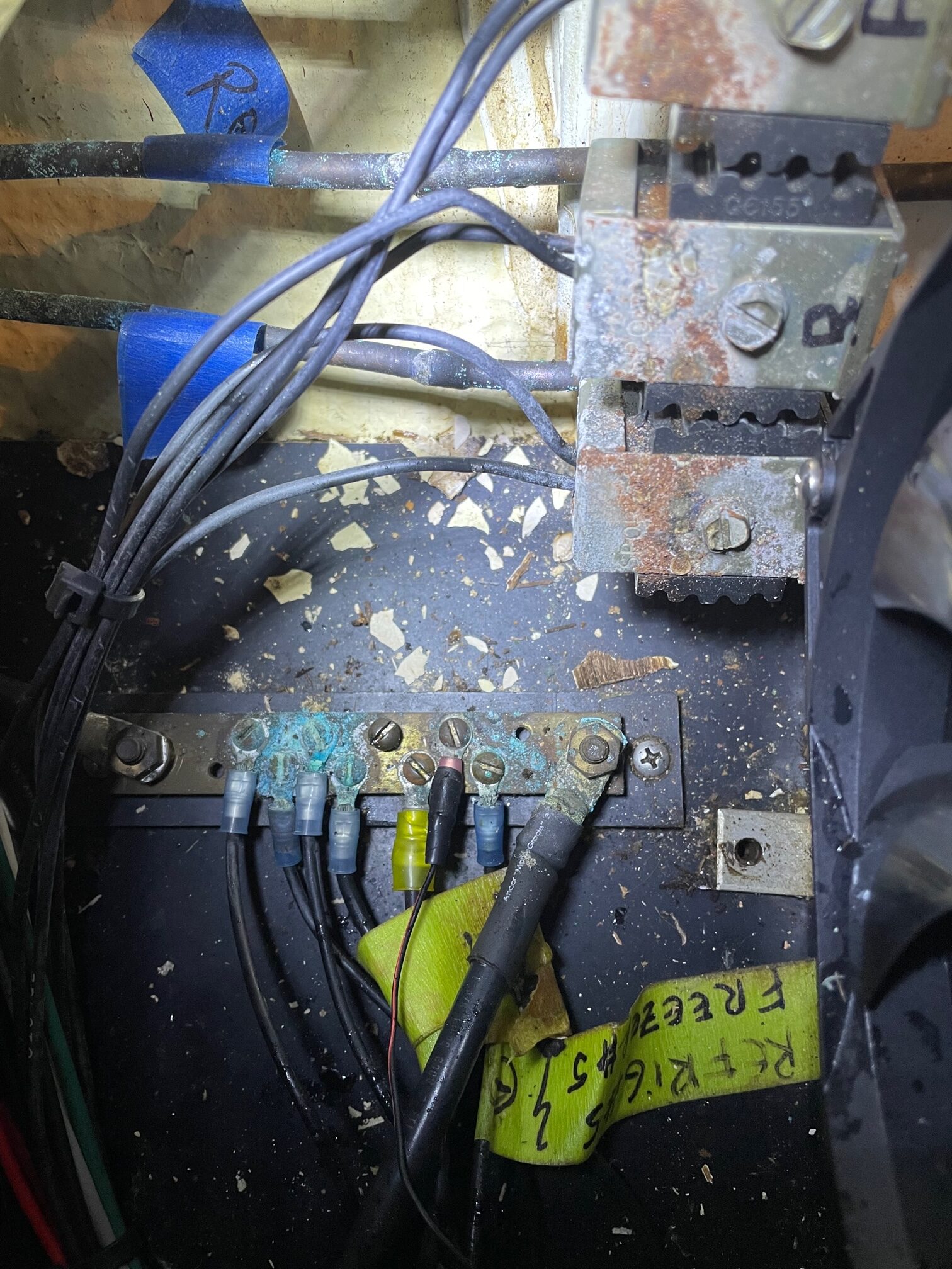
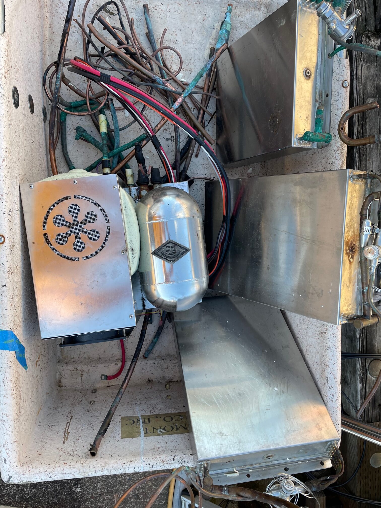
First I had to remove the old system. The holding plates came out easily and I was surprised how little refrigerant came out when I cut the copper tubing on the holding plates. I had always suspected a leak in the system so either it leaked out or settled in the tank or holding plates. The compressor unit was mounted under the pilot berth in a “dry” bay, but signs of moisture and corrosion were obvious.
Refrigeration CompressorGround Bus and Solenoid ValvesDock Cart Full of Old Refrigeration Equipment
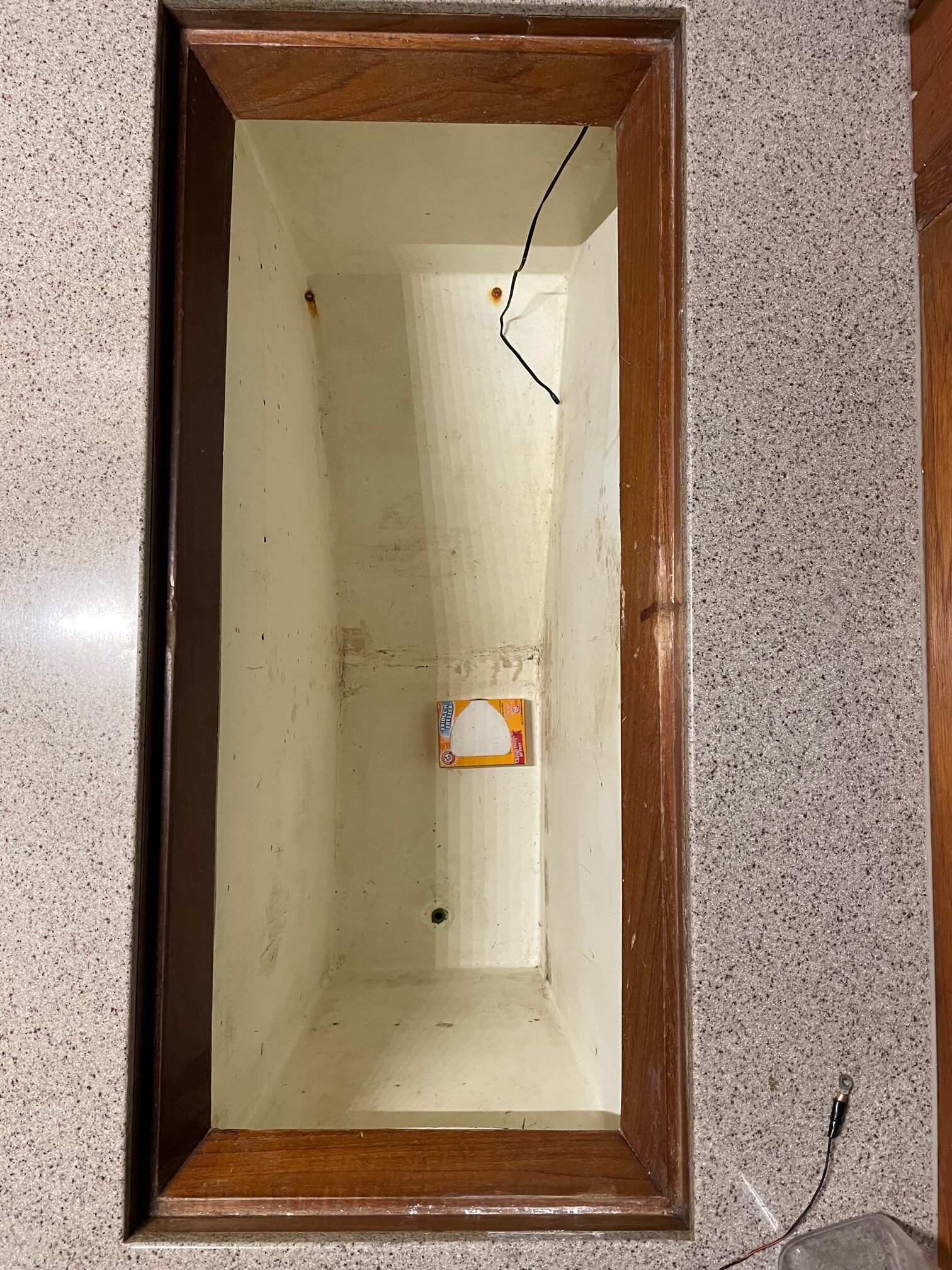
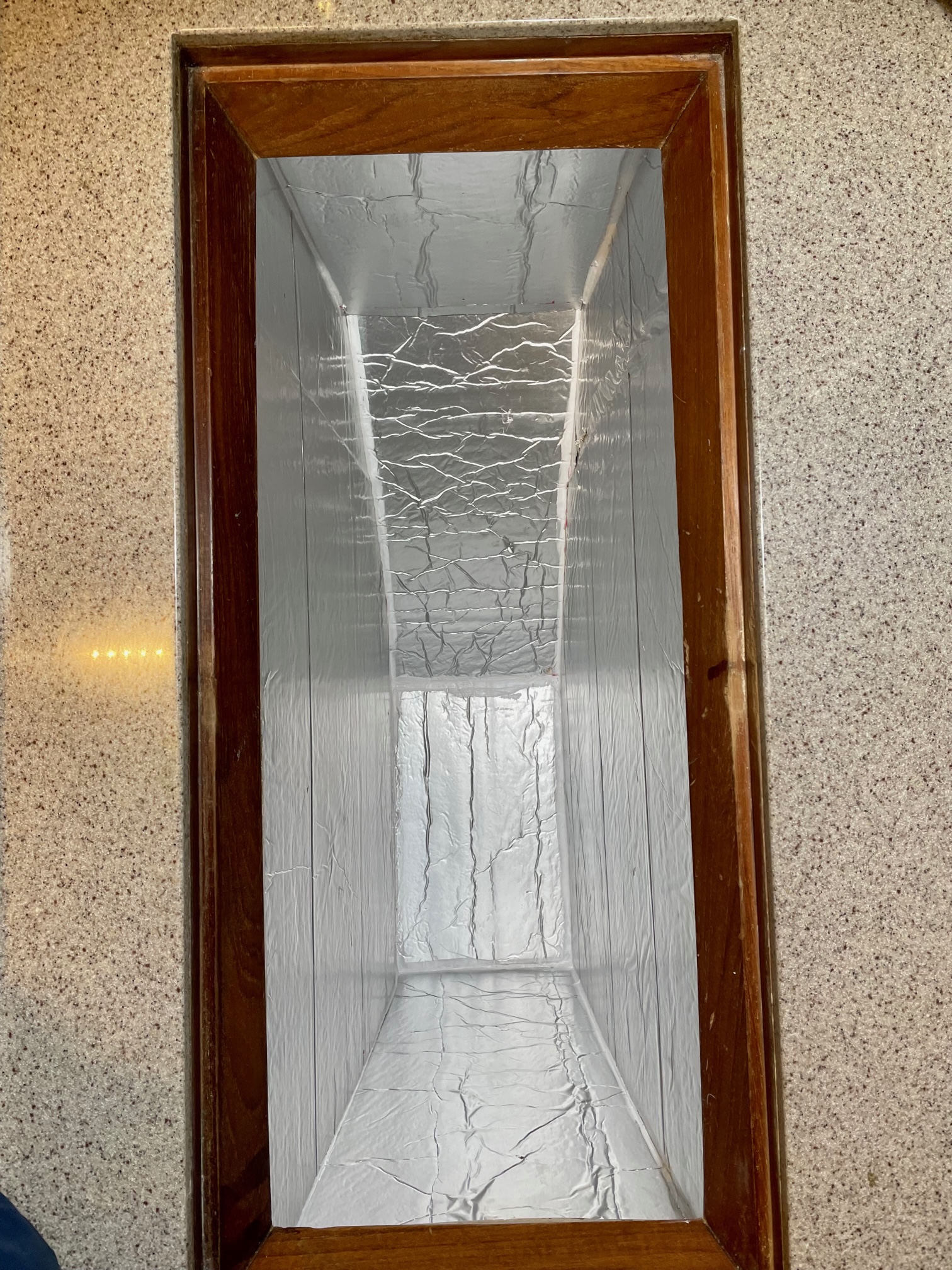
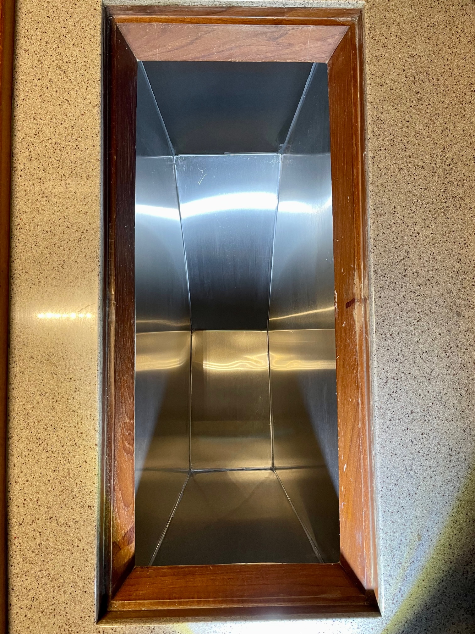
After removing all the old equipment and cleaning, the next step was to insulate the box. Without insulation, the box measured about 7 cubic feet. I used 2″ thick closed cell insulation (R factor of 12.5) for the bottom and 2 sides (hull side and engine side). For the large sides (fore and aft) I intended to use 2″ but after seeing how much smaller it made the box, I compromised with 1″. Since the box is top loading, we stack lock-n-lock boxes to organize the food (one for meat & cheeses, one for soda cans, one for condiments, etc), and they fit perfectly with the 1″ insulation on the sides (the box would have been too narrow if I had used the 2″). After fitting the insulation, I caulked all the seams to fill in any air gaps. Next I covered the insulation with 20 gauge stainless steel to protect it and make it easy to clean the inside of the box. For this, I made a cardboard template of all the sides and took them to Ballard Sheetmetal for cutting. It fit perfectly so I used adhesive to hold them in place, then caulked all the seams with grey silicone caulking. The final refrigerator box measurements came to 5.9 cubic feet, so I lost about 1.1 cubic feet from the insulation, but this should be a big improvement since the system won’t be cycling on as much.
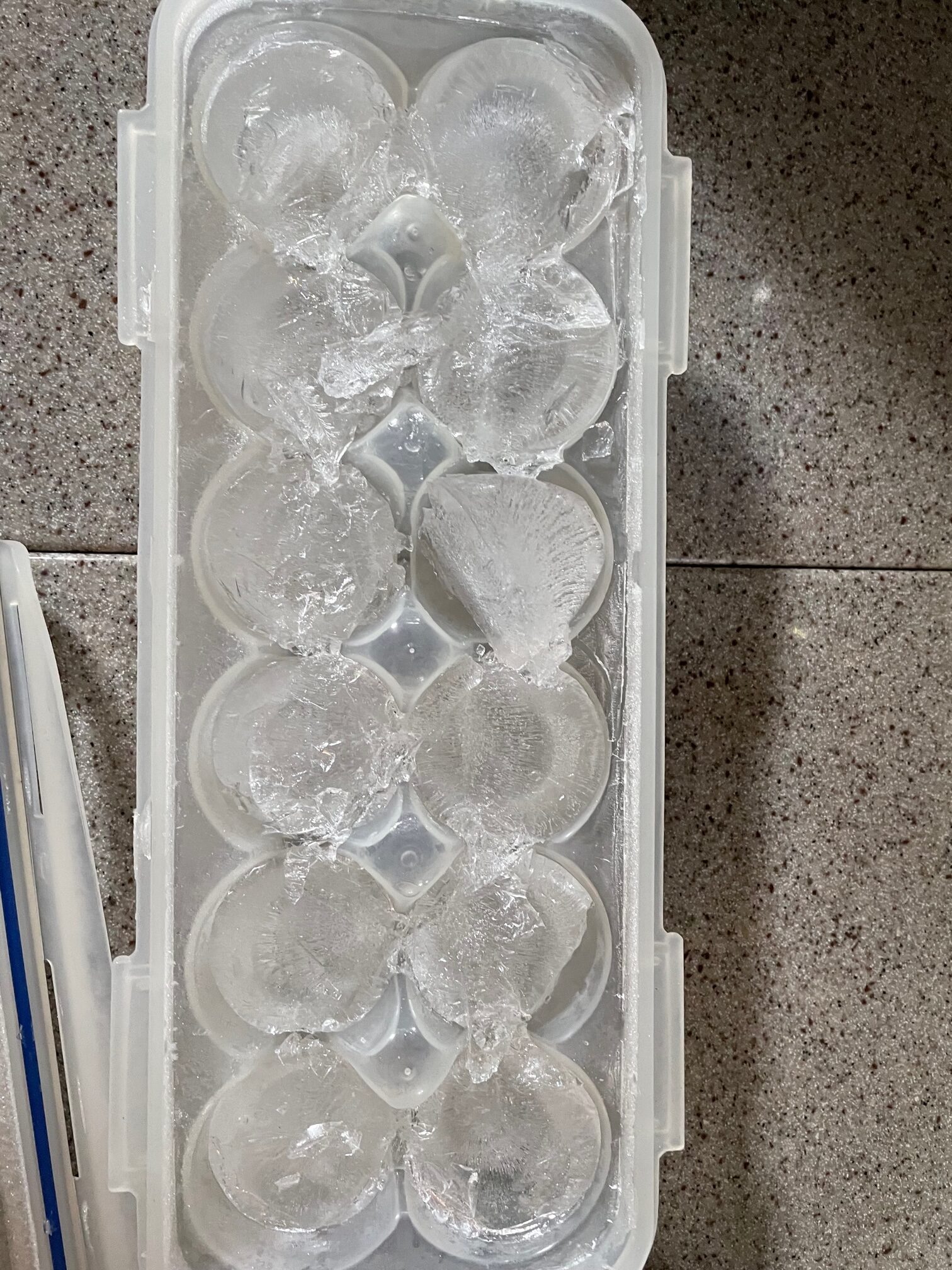
Installing the compressor was easy. I ran the refrigerant lines from the evaporator box and connected them with quick-connect couplers, then ran the input and output seawater hoses for cooling, and connected a fused 12V supply. These were already in place from the old system. The old system required an external water pump, so I bypassed the old pump to feed seawater directly from an existing thru-hull. I used the old temperature probe and digital display from the old system so I can monitor the temperature inside the box. Everything worked when I turned it on and the O-evaporator box easily freezes water so we’ll have ice cubes now!