Note: This post is probably not interesting or relevant to most readers–it’s a detailed account of a specific project that I put a lot of time and effort in. Some boat owners may find it useful if they have a similar problem.
The project began over 2 years ago when I returned to my boat in Fiji and discovered the masthead wind sensor was gone, thanks to Cyclone Winston. The sensor was part of the Simrad IS-15 wind/speed/depth/rudder position system that uses the NMEA 0183 protocol. Unfortunately, B&G (formerly Simrad) didn’t have replacement IS-15 wind sensors, so I bought the newer IS-20 sensor along with the necessary parts needed to convert an NMEA 2000 signal to an NMEA 0183 signal needed by the wind display instrument. Many hours were spent trying to get the new wind sensor to move the indicator on the display, but to no avail. We ended up sailing over 6000 nautical miles from Fiji to Seattle without any wind speed/direction.
Back in Seattle, I re-started the effort to get the wind sensor working. I brought the system home and set it up on the kitchen table to debug the problem. I used the diagram from B&G tech support shown below. It’s not very complicated, but it still didn’t work.
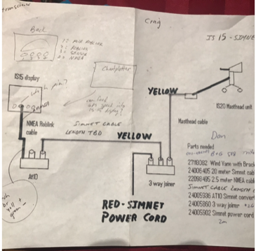
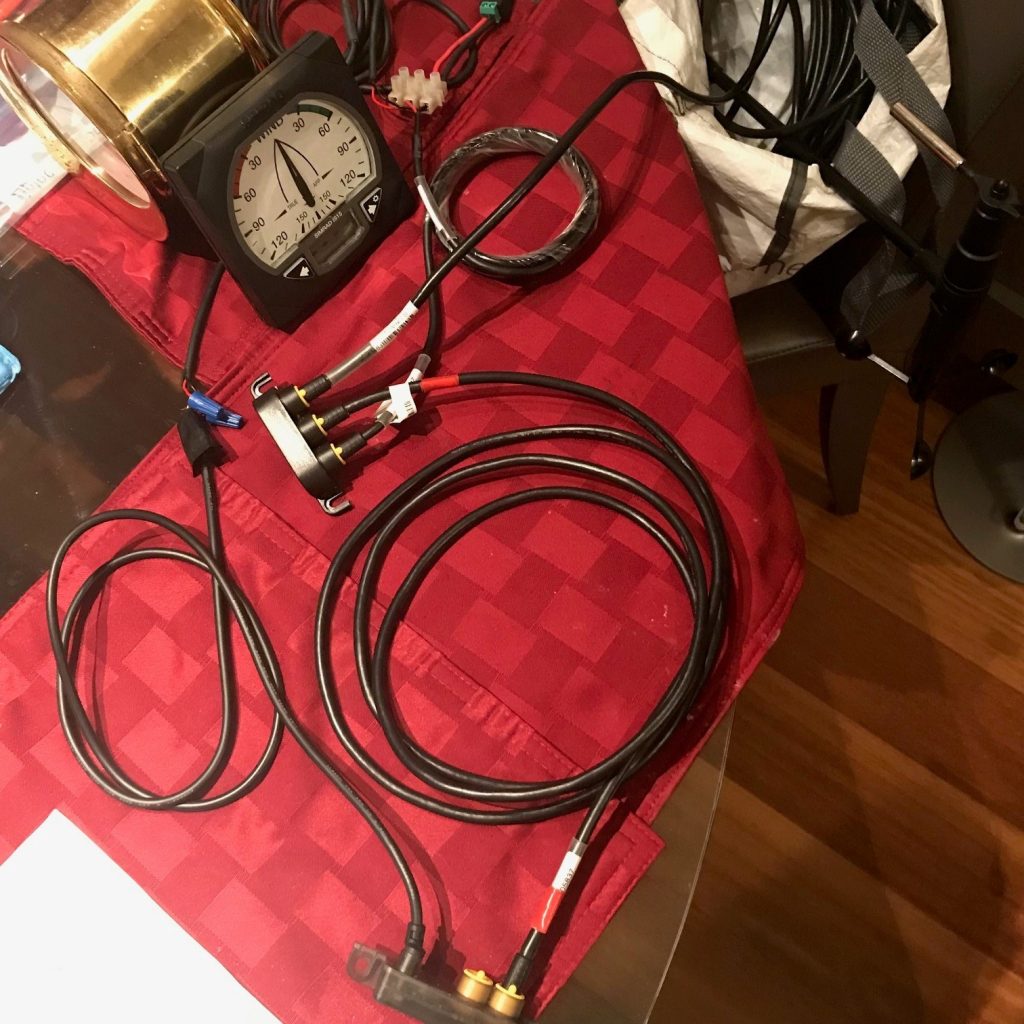
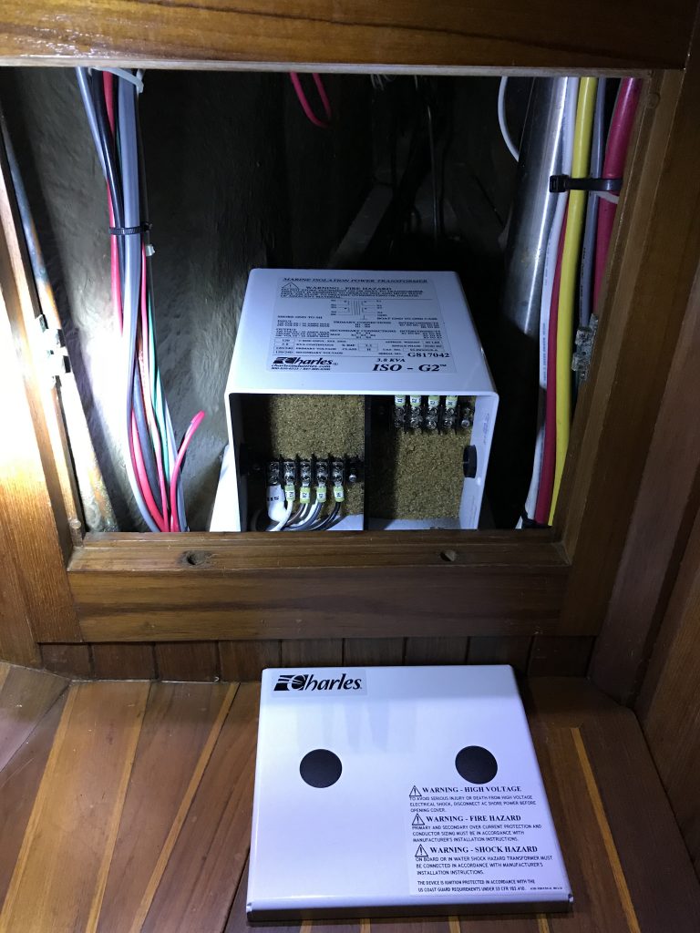
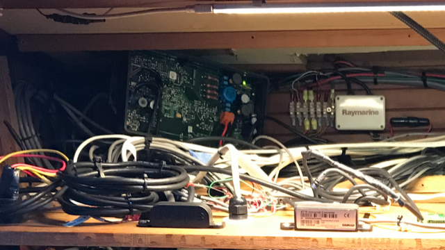
There are 2 parts used to convert the signal from NMEA 2000 to NMEA 0183–a 3-way joiner and an AT10. Since the system still didn’t work, I suspected I had a bad part so I bought a new AT10 and then it worked! After I had the system shown in the diagram working, I took it back to the boat to install. But there was 1 more piece to the system, a Simrad transceiver with inputs for wind, speed, and depth that multiplexes to a single output that goes to the wind, speed, and depth display instruments. Since the transceiver is installed at the navigation station (behind the main panel), I installed the 3-way connector and AT10 next to it (shown in the picture below with the transceiver box cover off).
Next was to run the wire from the 3-way joiner to the mast head where the wind sensor will be installed. Unfortunately, the existing wire and connectors were not compatible with the new wind sensor. The first step was to run the wire to the base of the compression post, about 15 feet away. This section went through cabinets and the settee before reaching the bilge near the base of the compression post. I cut the wire there and installed a junction box for easy disconnect when pulling the mast.
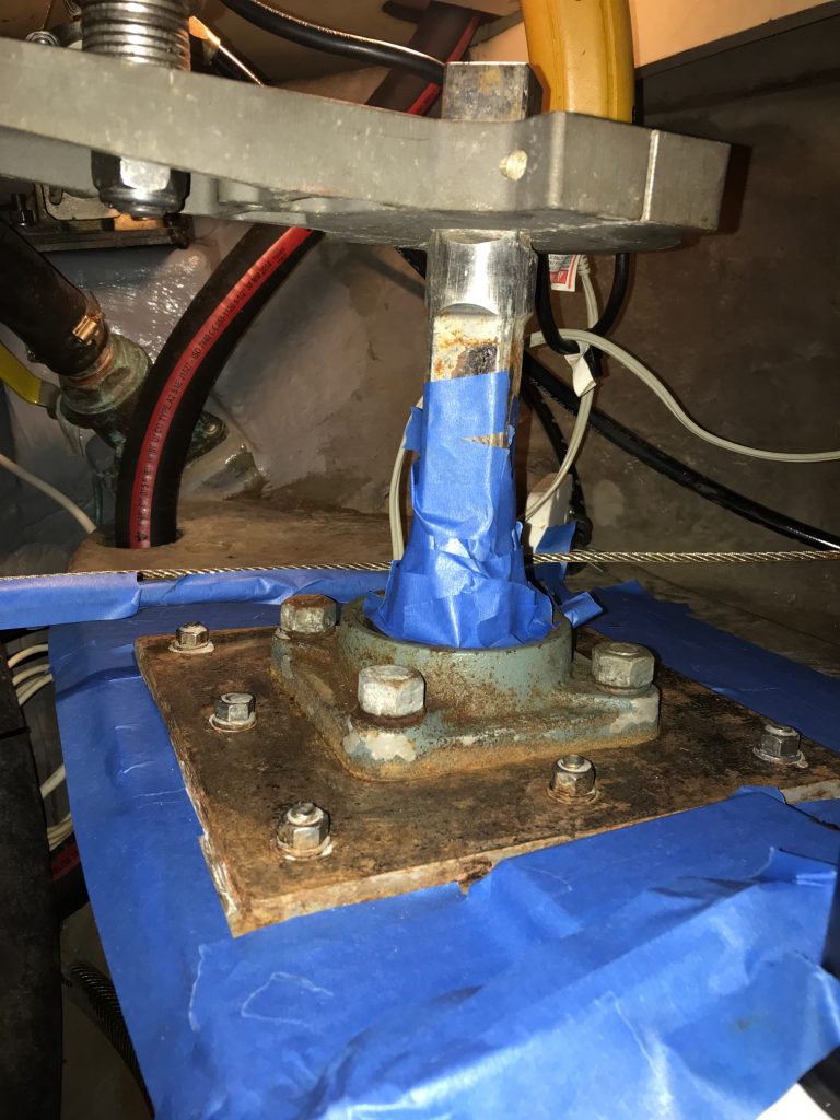
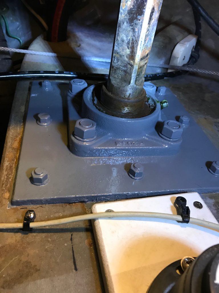
The final step was to pull the new wire through the compression post and up the mast. This turned out to be impossible because the existing wire would not budge either way. There are a total of 6 wires going through the compression post and mast for 2 spreader lights, a vhf antenna, masthead running, strobe, & anchor lights, a steaming light, and the wind sensor. Inside the mast, they are run in a conduit along the aft side of the mast. I suspected the wires could be taped together inside the mast as they exit the compression post and make 90 degree bends before they enter the conduit as the reasons for not being able to pull the existing wire. I considered pulling the deck-stepped mast to do the wiring, but the cost was going to be close to $1000 (crane fees, rigger fees) plus a whole lot of work (removing sails and boom, disconnecting all the wiring, loosening all the stays, getting the boat to yard). Since the cost and amount of work didn’t seem worthwhile for running a single wire, I thought of an alternative.
I purchased an endoscope for $40 on Amazon (Depstech Semi-Rigid Wireless Borescope WiFi Inspection Camera 2.0 Megapixels HD 1800mAh Lithium Battery Snake Camera – Yellow 11.5FT ). It uses a Wifi connection to display the camera images on smartphones. 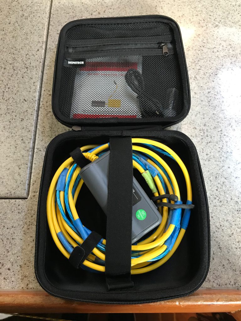
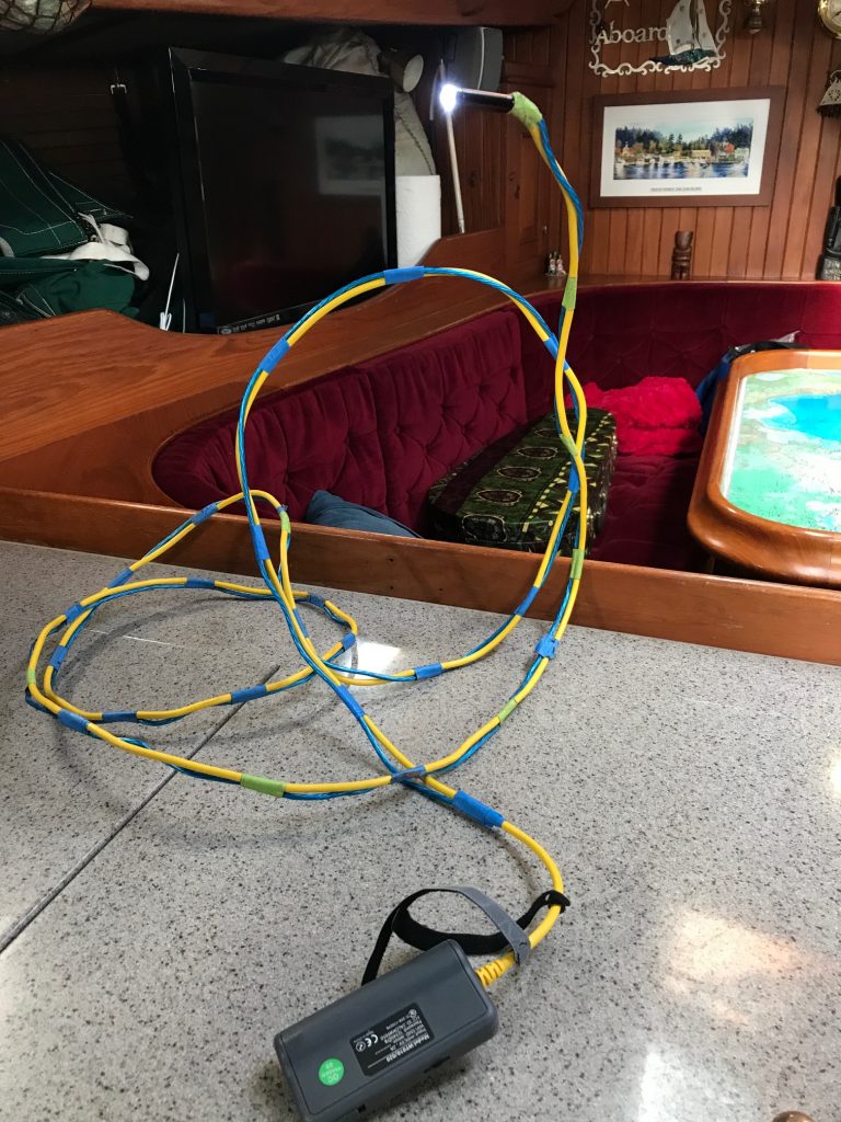 My plan was to feed the endoscope down a halyard exit hole on the side of the mast about 6′ above deck level to see what the wiring looked like near the mast base. The first thing I noticed was the 11′ semi-rigid wire was too flimsy, especially when feeding it long distances. So I taped an 11′ plastic-coated wire along side it to give it more rigidity. It took some practice but I was able to manipulate it to see the wiring near the bottom of the mast where it exits the conduit. The focal point of the camera lense is about 6″ and the intensity of the blue LEDs can be adjusted. I took video and pictures, below are some of the pics.
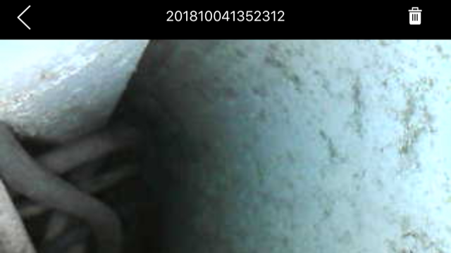
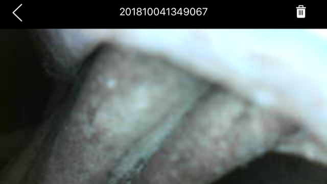
The top pic shows most of the wires as they exit the compression post. The smaller diameter grey wire is the wind sensor wire. The bottom pic shows the wires exiting the mast conduit and the smaller grey wire can be seen between the 2 larger diameter spreader light wires.
Next I decided instead of pulling the mast, I would cut a 7/8″ diameter hole about 3″ from the base of the mast to try to get a better view of the wiring. My mast is 3/8″ aluminum, plenty thick enough for a small access hole to have no affect. This allowed me to get a better shot of the wiring with the boroscope, and sure enough the wires were taped together in a bundle right as they exit the compression post.
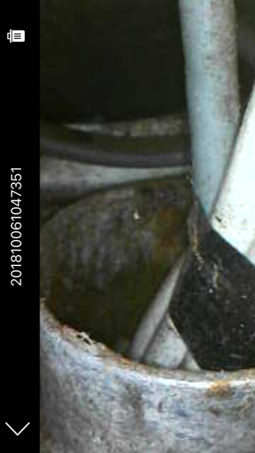
The 7/8″ hole allowed me to use a long screwdriver to break the electrical tape then grab the grey wind sensor wire with needle-nose pliers and pull it out the access hole. Next I taped a feeder string to the end of the grey wire at the bottom of the compression post (in the bilge), and pulled it up through the compression post and out the hole. Then I taped the new wind sensor line to the feeder string to pull the new line. I had to tug on the feeder line quite hard to squeeze the larger diameter connector on the end of the wire through, so I also used some thin black tarred seine twine to tightly wind over the tape to make sure it didn’t slip as I pulled. I also used liquid soap along the length of wire to make it more slippery. It all worked as planned and I pulled about 75′ of wire from the bilge to the access hole at the base of the mast.
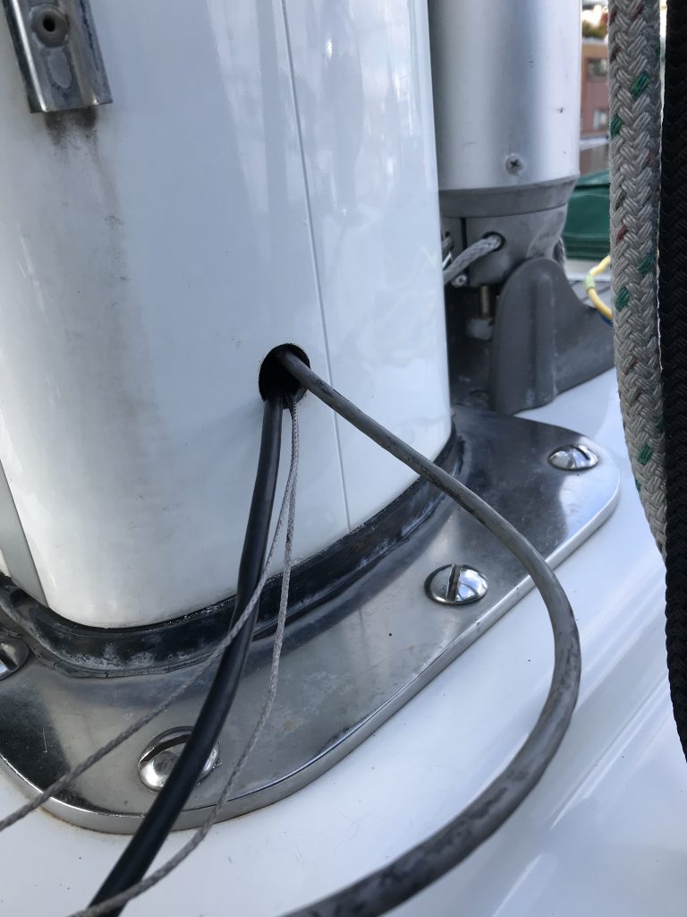
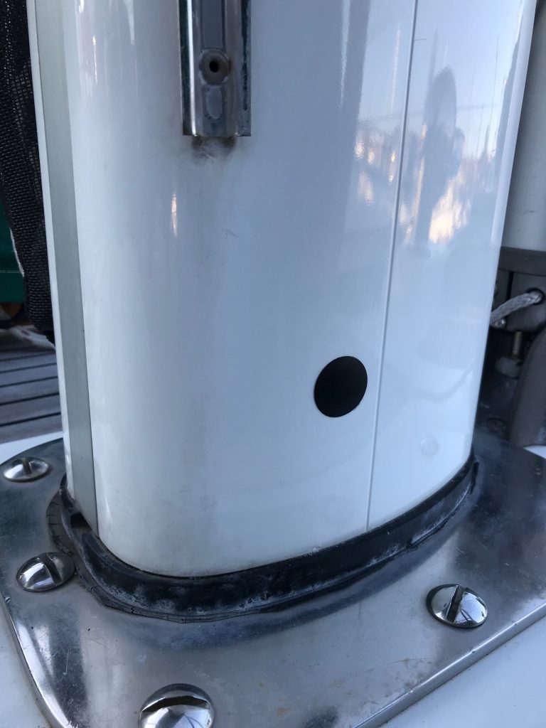
Here’s a picture of the access hole on the starboard side of the mast with the new NMEA 2000 wire (black) coming out. The old NMEA 0183 wire (grey) goes to the mast head and will be used to pull the new wire 58′ up the mast. The dynema string is a tracer pull-line through the compression post that will be left in case it’s needed in the future. After the wire was pulled up the mast, I capped the access hole with a plastic cap.
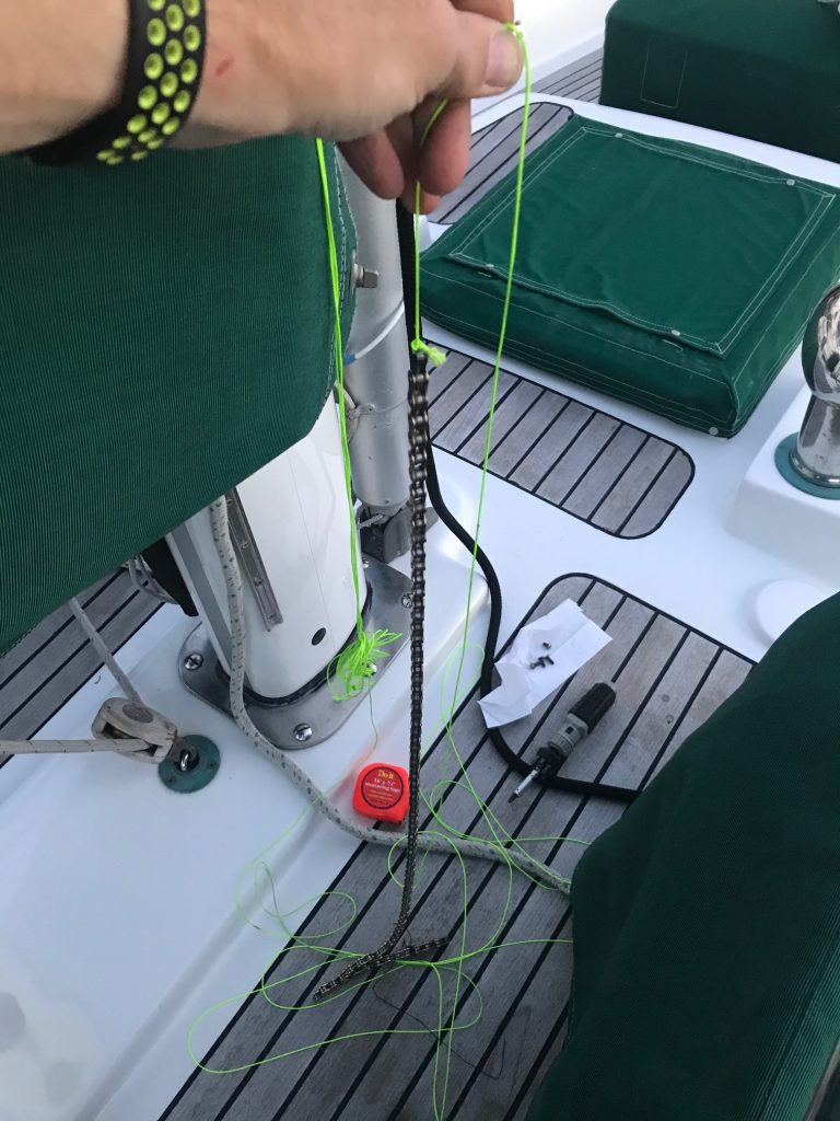
The final step was to run the wire up the mast. I thought it would be easy. I was wrong. Since I could not pull the old wire up though the conduit, I decided to run the new wire inside the mast (but not in the conduit). So I bought a bicycle chain to tie onto the end of a string and lowered it from the top of the mast. The weight and flexibility of the 3′ bike chain allowed the feeder string to go all the way down the mast to the base, where I was able to fish it out the access hole. So far, so good. Next I fastened 3 long zip ties around the wire about every 10 feet. By not cutting the ends off the zip ties and offsetting them by 120 degrees, this trick should buffer the wire from hitting the sides of the mast as the boat rolls and pitches. Next I securely taped the new wire to the bike chain, then went up the mast again to pull it up. About half way up the mast, it got stuck! Since I couldn’t pull it up (I tugged as hard as I dared) , I tried lowering it but it wouldn’t go down by gravity. I went back down to deck level and tried to pull it down, but it was stuck. I finally pulled hard enough to free the wire from the chain. Since my string was 100′ long, I decided to feed down more string from the top of the mast. Gravity took it all the way down to the bottom, where I was able to fish it out the access hole. Next I tied the new wind sensor wire to the string, returned to the top of the mast, and successfully pulled it all the way up the mast. I mounted the new wind sensor at the masthead on a quick release bracket and plugged the wire into the sensor, flipped on the navigation equipment, and the wind instrument came to life, showing speed and direction! Success. Sort of. The bloody chain was still stuck somehow/somewhere inside the mast, with a string attached to it the came out the top of the mast. I tested all the halyards that run internal to the mast and they all move fine. My only thought is that there must be some pinch point near the spreaders that has wedged the chain. For now, I’m leaving it. I’m taking the boat out sailing tomorrow and will enjoy the wind instrument and try not to think about the chain that is stuck somewhere inside the mast! Another project for another day….
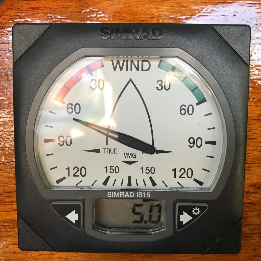
UPDATE: When I pulled up the drifter halyard today, the chain that was stuck inside the mast came tumbling down to the base of the mast and I was able to fish it out the small access hole. Problem solved!
